
Single outstretch pole magneto-rheological damper with annular piston

A magneto-rheological damper and annular piston technology, which is applied in the direction of vibration suppression adjustment, non-rotational vibration suppression, etc., can solve the problems of shortening the effective stroke of the piston and occupying length and space

Inactive Publication Date: 2010-10-20
谭晓婧
View PDF1 Cites 11 Cited by
  • Summary
  • Abstract
  • Description
  • Claims
  • Application Information

AI Technical Summary

Problems solved by technology

[0002] The current piston magneto-rheological damper is mainly divided into single-rod magnetorheological damper and double-rod magnetorheological damper; the double-rod magnetorheological damper is symmetrically installed at both ends of the piston with two identical diameter of the piston rod, when the piston moves in the cylinder, one piston rod enters the working cylinder while the other piston rod exits the working cylinder, so the volume in the working cylinder remains unchanged; Because the damper is only equipped with a piston rod at one end of the piston, when the piston moves in the cylinder, the volume in the working cylinder will change due to the piston rod entering and leaving the working cylinder. In order to work normally, it is necessary to compensate the change in the internal volume of the working cylinder when the piston rod enters and exits the working cylinder. The current single rod magneto-rheological damper usually uses an air bag in the working cylinder to compensate for the change in the internal volume of the working cylinder. Such as: Chinese patent 022231250 and Chinese patent 200510060298.6, all are that the bottom of the working cylinder is provided with an air bag to compensate the volume change in the working cylinder; although this method of setting the air bag at the bottom of the working cylinder can compensate the piston rod when entering and leaving the working cylinder It causes the change of the internal volume of the working cylinder, but because the compensation air bag is set at the bottom of the working cylinder, it takes up the length space in the working cylinder and shortens the effective stroke of the piston.

Method used


Image

  • Single outstretch pole magneto-rheological damper with annular piston
  • Single outstretch pole magneto-rheological damper with annular piston
  • Single outstretch pole magneto-rheological damper with annular piston

Examples


Embodiment Construction

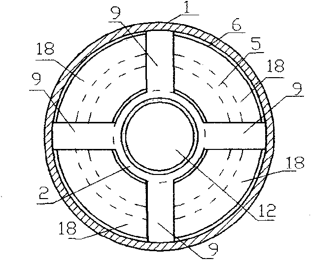
[0013] see figure 1 with figure 2 , the working cylinder 1 of the single-rod magnetorheological damper with annular piston has an inner and outer two-layer structure, wherein, the inner layer 2 of the working cylinder 1 has a piston 12, the middle part of the piston 12 is wound with a coil 19, and one end of the piston 12 is fixed Piston rod 15 is arranged, and piston rod 15 stretches out from one end of working cylinder 1 through sealing ring 13 and bearing 14, and the wiring terminal 17 of coil 19 is drawn through the center through hole 16 of piston rod 15; The inner layer 2 of working cylinder 1 and An annular piston 6 is installed in the annular cavity 20 between the outer layers 3, a sealing ring 8 and a positioning ring 7 are arranged on the outer circumference of the annular piston 6, and a sealing ring 10 and a positioning ring 11 are arranged on the inner circumference of the annular piston 6. A spring 5 is installed in the piston 6; a hole 18 for the flow of magne...


PUM


Abstract

The invention discloses a single outstretch pole magneto-rheological damper with an annular piston. A working cylinder of the single outstretch pole magneto-rheological damper with the annular piston has an inner-layer structure and an outer-layer structure; the annular piston is installed in an annular cavity between an inner layer and an outer layer of the working cylinder; and the annular piston is used for compensating volume change in the working cylinder caused when a piston rod enters and departs from the working cylinder so as to increase the working stroke of the magneto-rheological damper.

Description

technical field [0001] The invention relates to a magnetorheological damper, in particular to a single-rod magnetorheological damper with an annular piston. Background technique [0002] The current piston magneto-rheological damper is mainly divided into single-rod magnetorheological damper and double-rod magnetorheological damper; the double-rod magnetorheological damper is symmetrically installed at both ends of the piston with two identical diameter of the piston rod, when the piston moves in the cylinder, one piston rod enters the working cylinder while the other piston rod exits the working cylinder, so the volume in the working cylinder remains unchanged; Because the damper is only equipped with a piston rod at one end of the piston, when the piston moves in the cylinder, the volume in the working cylinder will change due to the piston rod entering and leaving the working cylinder. In order to work normally, it is necessary to compensate the change in the internal vo...

Claims


Application Information

Patent Timeline
IPC IPC(8): F16F9/53
Inventor 谭和平谢宁谭晓婧
Owner 谭晓婧
Learn More