Centralized driving LED colored lantern lighting device

A centralized drive and lighting device technology, applied in the field of lighting, can solve the problems of inconvenient adjustment of brightness and color, low power utilization efficiency, and large number of drivers, etc., to reduce overall complexity, high power utilization efficiency, and lower technical requirements Effect

Inactive Publication Date: 2010-10-20
FOSHAN CITY NANHAI DISTRICT LIANHE GUANGODNG XINGUANGYUAN IND INNOVATION CENT
View PDF5 Cites 2 Cited by
  • Summary
  • Abstract
  • Description
  • Claims
  • Application Information

AI Technical Summary

Problems solved by technology

In this lighting device, each LED lantern needs a driver, and the driver converts the power supply into a specific current as the driving current of the corresponding LED lantern. The number of drivers is large, the space is large, the cost is high, and the power utilization efficiency is high. Low, and it is not convenient to uniformly adjust the brightness and color of the lighting device

Method used


Image

  • Centralized driving LED colored lantern lighting device
  • Centralized driving LED colored lantern lighting device
  • Centralized driving LED colored lantern lighting device

Examples


Embodiment 1

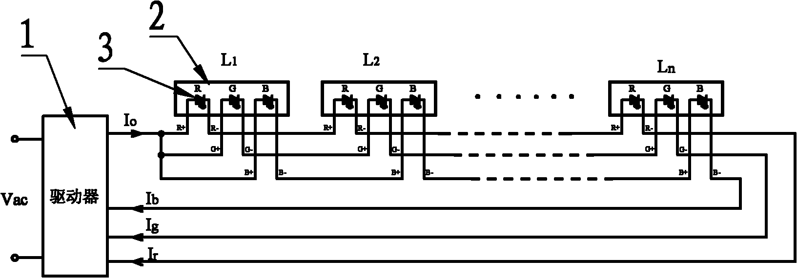
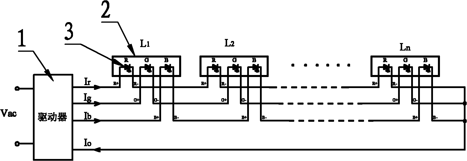
[0035] refer to figure 2 , the lighting device for intensively driving LED colored lights of the present invention includes a driver 1 and at least two LED colored lights 2, the LED colored lights 2 in this example are RGB colored lights, represented by L, there are N LED colored lights 2 , then use L1, L2,..., Ln to represent. There are R light source tubes, G light source tubes and B light source tubes in the RGB color lamp L, each light source tube 3 is provided with at least one, and the light source tubes 3 of the same color of each LED color lamp 2 are connected in series to form a corresponding series branch. Each series branch is driven by the same driver 1, and the two ends of each series branch are connected to the two output terminals of the driver 1.

[0036] Wherein, the number of each light source tube 3 in each LED lantern 2 may be one, or at least two. If each color light source tube 3 in each LED color lamp 2 is provided with one, the series branches are re...

Embodiment 2

[0044] Embodiment 2 is basically the same as Embodiment 1, the difference is that the LED colored light 2 in this example is a WIED colored light, and the WIED colored light is not only provided with the same RGB light source tube as in Embodiment 1, but also has a W light source tube .

[0045] Such as Figure 5 As shown, the same W light source tubes are connected in series to form a W series branch. The positive end of the W series branch is connected to the output high potential end of driver 1, and the negative end is connected to the output low potential end of driver 1. The current from the output low potential end Driven by Iw, it is a common positive terminal connection mode, and the output current Io of the high potential terminal is the sum of Ir, Ig, Ib, and Iw.

[0046] Such as Figure 6 As shown, it is the connection mode of the common ground terminal. The positive terminal is connected to the output high potential terminal of driver 1, and the negative termina...


PUM


Abstract

The invention provides a centralized driving LED colored lantern lighting device, belonging to the lighting technical field. The invention solves the problems that the existing LED colored lantern lighting device is provided with a plurality of drivers, occupies large space and has high cost and low electrical energy utilization ratio and is not convenient to uniformly regulate brightness and color of the lighting device. The centralized driving LED colored lantern lighting device comprises a driver and at least two LED colored lanterns, each LED colored lantern is internally provided with two light source tubes in different colors, at least one light source tube in each color is arranged, the light source tubes in the same color in each LED colored lantern are sequentially connected in series, so as to form a series branch, each series branch is driven by one driver, and the two terminals of each series branch are connected with corresponding output terminals of the driver. The invention can improve electrical energy utilization ratio, occupies small space and is convenient to uniformly and flexibly regulate the brightness and color of the entire lighting device and reduce cost.

Description

technical field [0001] The invention belongs to the technical field of lighting, and relates to a lighting device for LED colored lights, in particular to a lighting device for intensively driving LED colored lights. Background technique [0002] LED colored light is a kind of colored light in which LED light source tubes of various colors are arranged in the bulb shell, such as RGB colored light, and three kinds of color light source tubes are arranged in the bulb shell of an RGB colored light, namely R light source tube and G light source tube. tube and B light source tube, the R light source tube is a red light emitting diode, the G light source tube is a green light emitting diode, and the B light source tube is a blue light emitting diode. Another example is a WIED colored light. There are light source tubes of four colors in the bulb shell of a WIED colored light. In addition to the R light source tube, the G light source tube and the B light source tube, there is also...

Claims


Application Information

Patent Timeline
Patent Type & Authority Applications(China)
IPC IPC(8): F21S10/02F21V23/02H05B37/02F21Y101/02
CPCH05B33/0857H05B45/20
Inventor 华桂潮吴新科任丽君
Owner FOSHAN CITY NANHAI DISTRICT LIANHE GUANGODNG XINGUANGYUAN IND INNOVATION CENT
Why Eureka
Try Eureka