
Super-resolution optical imaging device and method

A super-resolution, optical imaging technology, applied in optics, optical components, instruments, etc., can solve the problems of unsuitable application and high light source cost, and achieve the effect of simple structure, small size and low cost

Inactive Publication Date: 2010-10-20
NANJING FANGYUAN GLOBAL DISPLAY TECH
View PDF0 Cites 4 Cited by
  • Summary
  • Abstract
  • Description
  • Claims
  • Application Information

AI Technical Summary

Problems solved by technology

[0005] According to the Rayleigh criterion, the resolution is proportional to the wavelength λ of the incident light in vacuum, and inversely proportional to the numerical aperture NA of the objective lens. Therefore, there are two traditional methods to improve the resolution: first, choose as short as possible Radiation wavelengths, such as using ultraviolet light, x-rays, electrons, etc., but these light sources are expensive and not suitable for some applications, especially biomedical applications; second, increase the numerical aperture, but if you do not consider the higher For oil immersion objective lenses (NA=1.5 or so) and solid immersion lenses that are rare and difficult to use, the maximum value of numerical aperture does not exceed 1. Therefore, using traditional methods, the resolution limit of far-field optics can only reach λ / 2 at the highest

Method used


Image

  • Super-resolution optical imaging device and method
  • Super-resolution optical imaging device and method
  • Super-resolution optical imaging device and method

Examples


Embodiment Construction

[0023] Below in conjunction with accompanying drawing, the technical scheme of invention is described in detail:

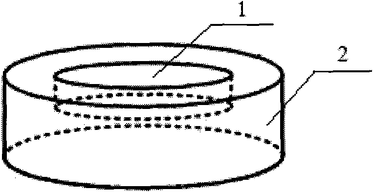
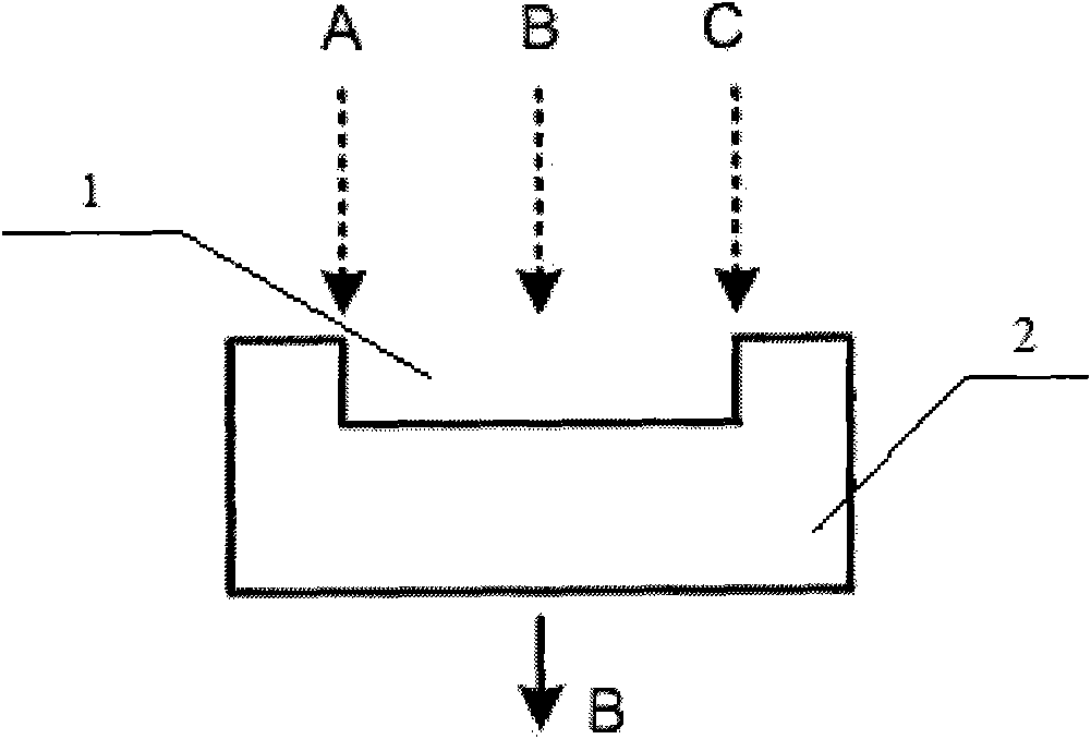
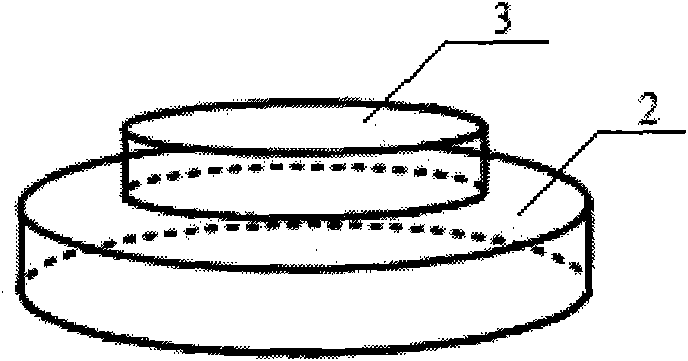
[0024] like Figure 1 to Figure 4 As shown, the present invention is a device and an imaging method thereof utilizing self-mixing interference to achieve super-resolution optical imaging, a substrate 2 made of a transparent material and a step 3 on the substrate 2 (or a groove 1 on the substrate 2 )constitute. The principle is: the imaging beam converges on the surface of the step 3 (or groove 1) under the action of the focusing lens, and part of the light is incident on the edge of the step 3 (or groove 1) and split by the wave surface. Step 3 (or groove 1) and the outgoing light path that does not pass through step 3 (or groove 1) are different, resulting in a phase difference. The height of the control step 3 (or groove 1) makes the phase difference of the two beams pi . When the two beams of light self-mix and interfere under the step 3 (or the groove 1), t...


PUM


Abstract

The invention discloses super-resolution optical imaging device and method. The super-resolution optical imaging device comprises a base. The base is provided with a groove (a step); the difference of optical paths passing through the groove (the step) and the edge of the groove (the outside of the step) is a half of the length of a light wave emitted by an imaging object due to the design of the depth of the groove (the height of the step); light beams positioned right above the groove (the step) are emitted to the bottom surface of the groove (the surface of the step); half of other light beams pass through the bottom surface of the groove (the surface of the step), the other half of the same pass through the edge of the base, and the light beams passing through the bottom surface of the groove (the surface of the step) and the edge of the base carry out self-mixing interference cancellation to obtain the information of the light beams positioned right above the groove on the base so as to break through a diffraction limit. The invention has small size and simple structure and realizes the super-resolution imaging.

Description

technical field [0001] The invention relates to a device and method for realizing super-resolution optical imaging based on self-mixing interference. Background technique [0002] Resolution in far-field optics is limited by diffraction effects. In 1873, German scientist Abbe (Abbe) deduced the diffraction resolution limit for the first time based on the diffraction theory, that is, the distance between two points that can be resolved optically is always greater than half of the wavelength. Later, Rayleigh summarized Abbe's diffraction theory into a formula: [0003] d ≥ 0.61 λ NA [0004] This is known as the Rayleigh criterion. This criterion shows that when the distance d between two points on the object is greater than or equal to the amount specified on the right side of the inequality, the image points of the two points on the object can be distinguished. Otherwise, the two image poi...

Claims


Application Information

Patent Timeline
Patent Type & Authority Applications(China)
IPC IPC(8): G02B27/58
Inventor 何浩培杨涛李千秋黄维蔡潮盛
Owner NANJING FANGYUAN GLOBAL DISPLAY TECH
Learn More