
Flight control system

A technology of flight control system and flight parameters, which is applied in control/adjustment system, non-electric variable control, position/direction control, etc., and can solve the problem of inability to accurately control the flight trajectory of the UAV and the flight distance of the UAV is limited to the visual In order to achieve the effect of precise control, increase the success rate and reduce the load due to problems such as the limitation of distance and visual observation ability

Inactive Publication Date: 2010-10-20
TSINGHUA UNIV
View PDF9 Cites 58 Cited by
  • Summary
  • Abstract
  • Description
  • Claims
  • Application Information

AI Technical Summary

Problems solved by technology

[0003] At present, the operator on the ground usually directly observes the flight attitude of the UAV through vision, and uses the radio remote controller to carry out remote control flight; this flight mode has great flexibility, but due to the limitation of the visual observation ability of the operator on the ground, The flight distance of the UAV can only be limited to the visual distance; and due to the limitation of personnel's perception of the geographical location, the flight trajectory of the UAV cannot be precisely controlled

Method used


Image

  • Flight control system
  • Flight control system
  • Flight control system

Examples


Embodiment Construction

[0044] In order to make the above objects, features and advantages of the present invention more comprehensible, the present invention will be further described in detail below in conjunction with the accompanying drawings and specific embodiments.

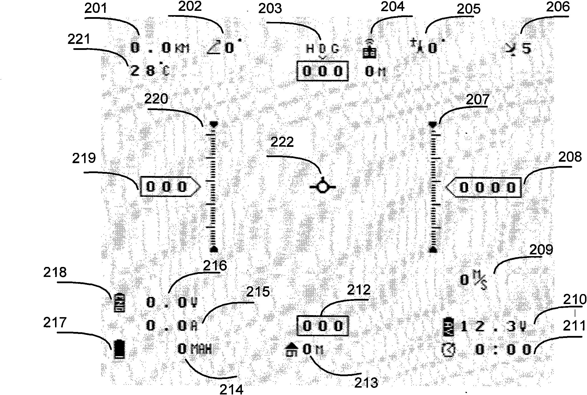
[0045] One of the core ideas of the present invention is to superimpose the flight parameters into the video signal, so that, compared with the prior art, the flight distance of the UAV in the remote control flight mode can only be limited to the visual distance, and the ground operator The video superimposed with flight parameters can operate the remote control without directly looking at the drone, so as to realize the remote control take-off and landing of the drone, which can effectively improve the success rate of take-off and landing of the drone.

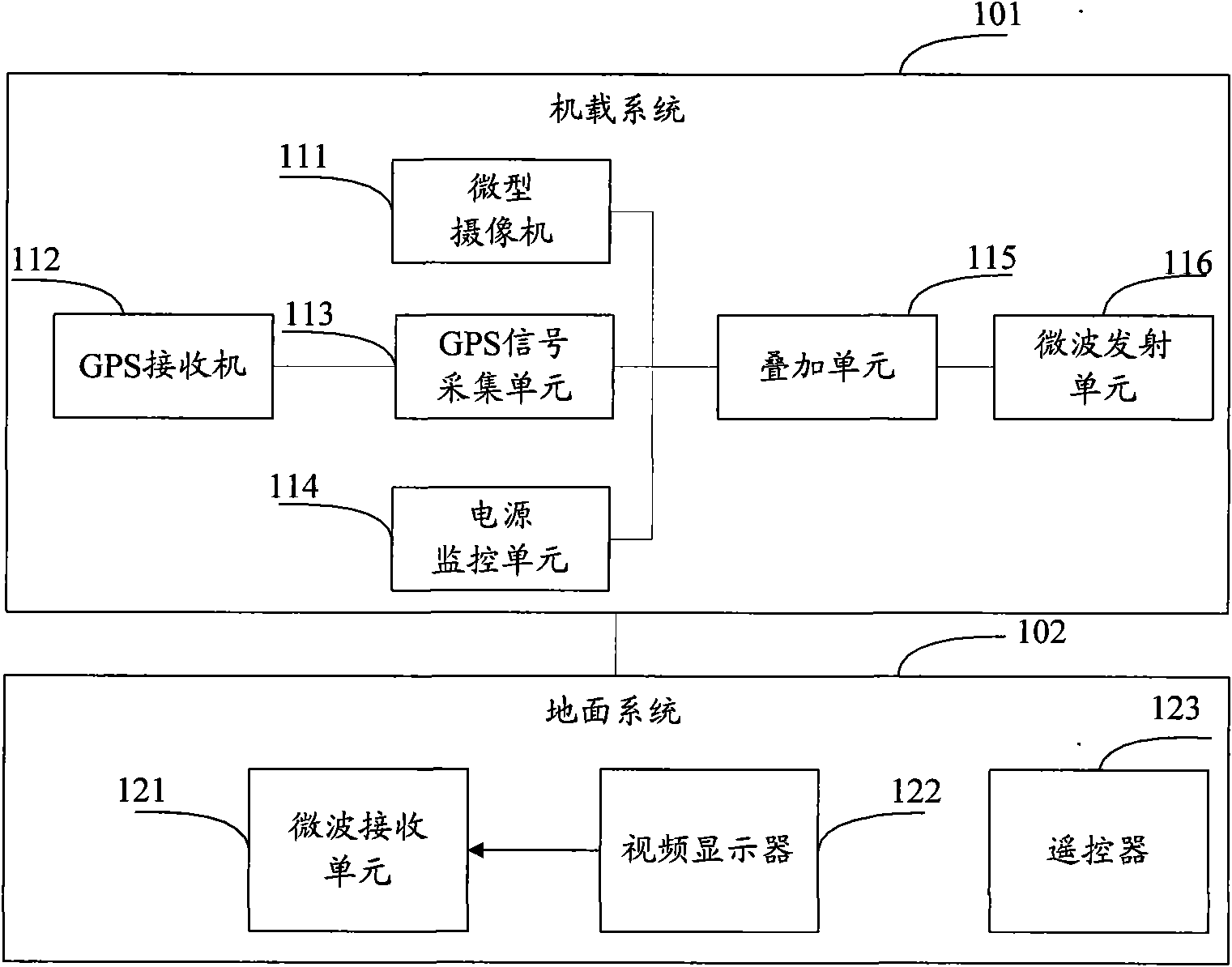
[0046] refer to figure 1 , shows a structural diagram of Embodiment 1 of a flight control system of the present invention, which may specifically include:

[0047] The airborne ...


PUM


Abstract

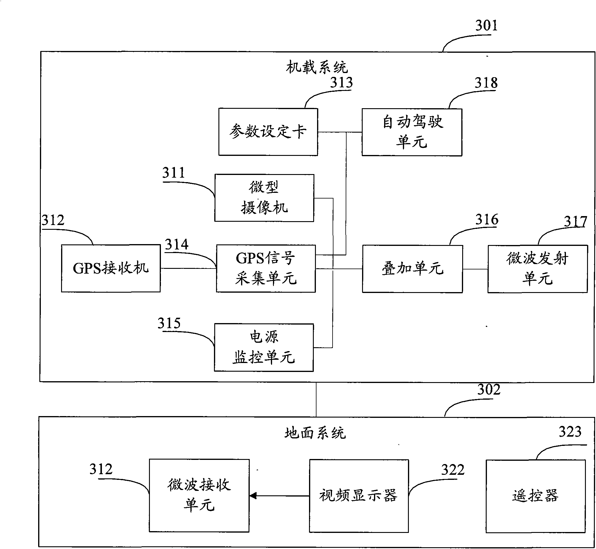
The invention provides a flight control system, which comprises an airborne system and a ground system, wherein the airborne system comprises a miniature video camera, a GPS receiver, a GPS signal collection unit, a power supply monitoring unit, an overlapping unit and a microwave emitting unit, the miniature video camera and the GPS receiver are arranged outside an unmanned plane, the GPS signal collection unit, the power supply monitoring unit, the overlapping unit and the microwave emitting unit are arranged inside the unmanned plane, and the ground system comprises a microwave receiving unit, a video display and a remote control, wherein the miniature video camera is used for monitoring video images right ahead the unmanned plane in real time, the GPS signal collection unit is used for collecting and processing data transmitted from the GPS receiver to obtain flight parameters, the power supply monitoring unit is used for detecting and obtaining the power supply information of the unmanned plane, the overlapping unit is used for overlapping the flight parameters and / or the power supply information onto the video images, and the microwave emitting unit is used for emitting the overlapping results to the ground system. The invention can perfectly control the unmanned plane.

Description

technical field [0001] The invention relates to the technical field of unmanned (unmanned) aircraft, in particular to a flight control system. Background technique [0002] Unmanned aircraft (unmanned aerial vehicle) is an unmanned aircraft controlled by radio remote control equipment or onboard computer program control system; its use cost is low, not only can complete the tasks performed by manned aircraft (manned aircraft), but also is suitable for Tasks that are not suitable for manned aircraft, such as reconnaissance in dangerous areas, air rescue command and remote sensing monitoring. [0003] At present, the operator on the ground usually directly observes the flight attitude of the UAV through vision, and uses the radio remote controller to carry out remote control flight; this flight mode has great flexibility, but due to the limitation of the visual observation ability of the operator on the ground, The flight distance of the UAV can only be limited to the visual ...

Claims


Application Information

Patent Timeline
Patent Type & Authority Applications(China)
IPC IPC(8): G05D1/00
Inventor 胡春华杨贵慈续立军严斌陈海昕葛东云
Owner TSINGHUA UNIV
Learn More