Flat solar battery bracket

A solar cell, flat-panel technology, applied in circuits, photovoltaic power generation, electrical components, etc., can solve problems such as damage to roof structure, damage, cracks, etc., and achieve the effect of increasing contact area, prolonging service life, and strengthening homogeneity.

Inactive Publication Date: 2011-11-23
钟坚
View PDF0 Cites 0 Cited by
  • Summary
  • Abstract
  • Description
  • Claims
  • Application Information

AI Technical Summary

Problems solved by technology

[0002] The main environment where the flat-panel solar cell bracket is used is the vacant flat roof of the building. The natural environment will inevitably be affected by the natural wind. When the strong wind blows the flat-panel solar cell from the back direction of the flat-panel solar cell It will cause lifting force, cause deformation, rupture and damage of flat-panel solar cells, and even overturn the entire flat-panel solar cells, and the vast majority of buildings are not allowed to be on the roof plane in order to prevent roof leakage or avoid damage to the building structure. Drill holes to mount brackets
[0003] The existing mechanically fixed flat-plate solar cell supports all use three to four feet to touch the ground to realize the structure of supporting the entire support, which has the following disadvantages: ①If you want to be firmly fixed on the roof plane of a building, you have to use Drill holes on the roof plane of the building to install, but this will damage the roof structure and cause water leakage; ②If it is installed without drilling, it is difficult to form a stable structure due to the small contact area between the three-to-four-leg support structure and the roof plane of the building. When hit by strong wind, it is easy to overturn the entire flat-panel solar cell and support; ③There is no wind-shielding facility to protect the back of the flat-panel solar cell, which is easily damaged by strong wind

Method used


Image

  • Flat solar battery bracket
  • Flat solar battery bracket
  • Flat solar battery bracket

Examples


Embodiment 1

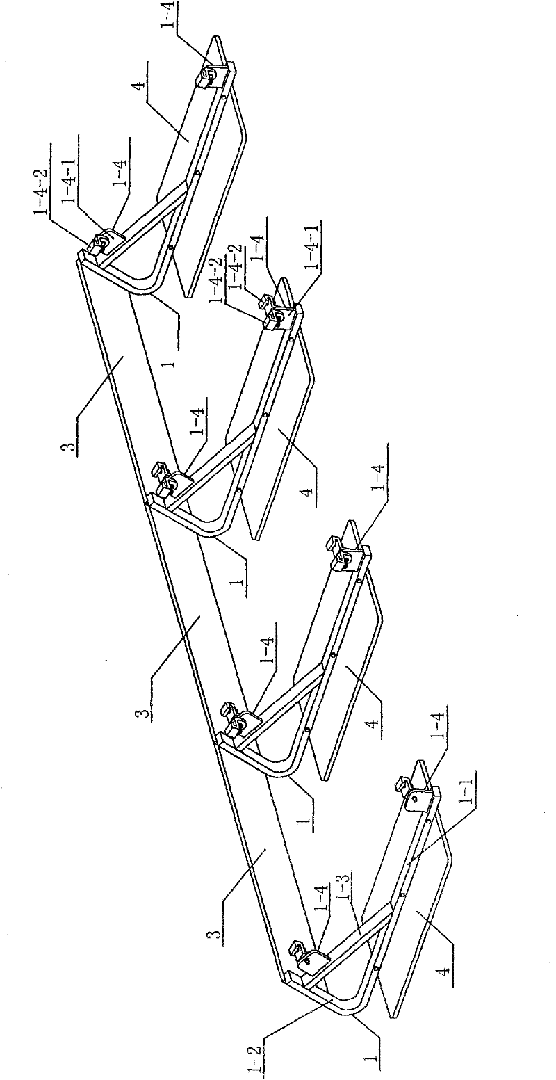
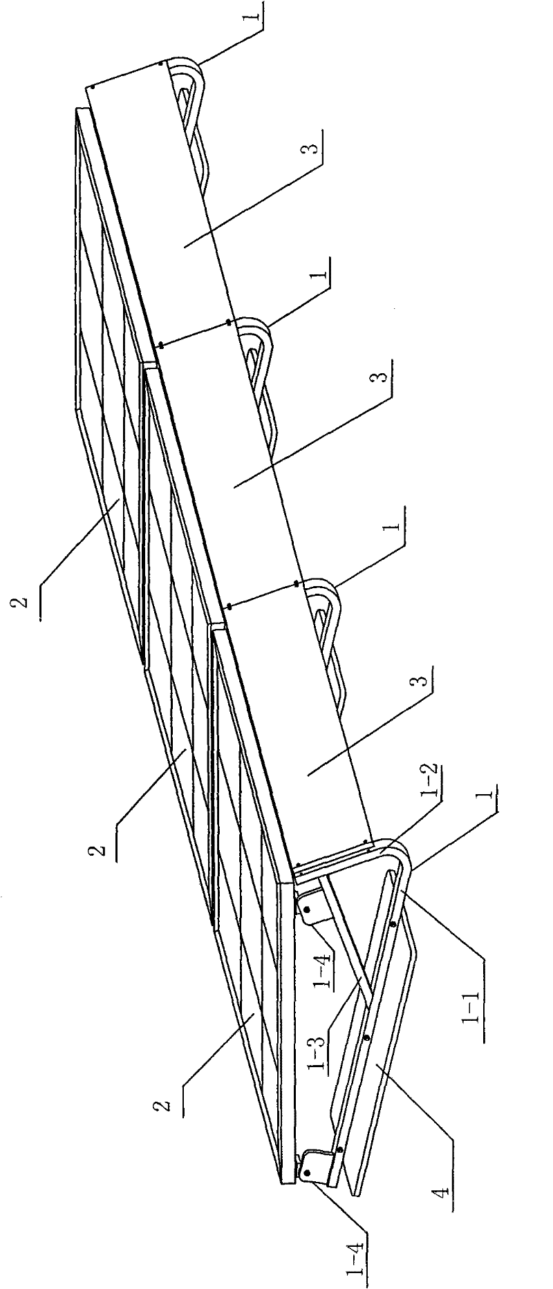
[0021] see figure 1 , figure 2 As shown, a flat-plate solar cell support, when three flat-plate solar cells need to be placed, four horizontal support feet 1 arranged side by side in the same direction are provided, and the space between two adjacent horizontal support feet 1 The spacing is the same as the width of the flat-plate solar cells 2, and each horizontal support foot 1 is composed of a horizontal beam 1-1, an oblique vertical beam 1-2, a supporting beam 1-3 and two support members 1-4, each The supporting part 1-4 is made up of a supporting seat 1-4-1 and a draw-in groove part 1-4-2. The horizontal beam 1-1 and the inclined vertical beam 1-2 are integrally formed by an aluminum profile, and the angle a between the horizontal beam 1-1 and the inclined vertical beam 1-2 is 50°. A support beam 1-3 is welded between the middle position of -1 and the middle and upper position of the inclined vertical beam 1-2, and a supporting seat 1-4-1 is welded on the end of the str...

Embodiment 2

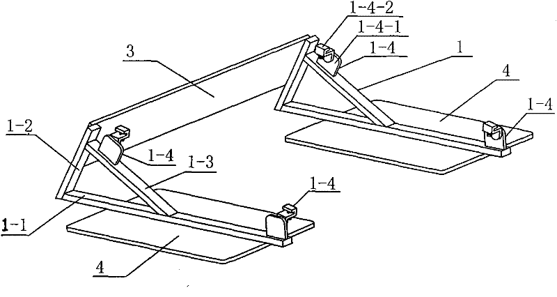
[0023] see image 3 , Figure 4 As shown, a flat solar battery support, when only one flat solar battery needs to be placed, two horizontal support legs 1 arranged side by side in the same direction can be used, and one of the two horizontal support legs 1 The distance between them is slightly smaller than the width of the flat-plate solar cell 2, and each horizontal support foot 1 is composed of a horizontal beam 1-1, an inclined vertical beam 1-2, a support beam 1-3 and two support members 1-4, Each supporting member 1-4 is made up of a supporting base 1-4-1 and a groove member 1-4-2. One end of the horizontal beam 1-1 is welded to the lower end of the inclined vertical beam 1-2, and the angle a between the horizontal beam 1-1 and the inclined vertical beam 1-2 is 40°. A support seat 1-4-1 is welded on the other end of the beam 1-1, and a supporting beam 1-4-1 is welded between the middle position of the horizontal beam 1-1 and the upper middle position of the inclined ver...


PUM


Abstract

The invention discloses a flat solar battery bracket which is provided with N+1 horizontal bracket feet which are arranged in parallel in the same direction, wherein each horizontal bracket foot is composed of a transverse horizontal beam, an oblique vertical beam, a supporting beam and supporting members, wherein one end of the transverse horizontal beam is fixedly connected with the lower end of the oblique vertical beam; an included angle alpha between the transverse horizontal beam and the oblique vertical beam is 30-60 degree; the other end of the transverse horizontal beam is fixedly connected with the supporting member; the supporting beam is fixedly connected between the transverse horizontal beam and the oblique vertical beam; and the supporting member is fixedly connected with the upper part of the supporting beam. Each flat solar battery is supported and fastened together by corresponding supporting members on two adjacent horizontal bracket feet. The flat solar battery bracket provides a new bracket structure, can prevent the back of the flat solar battery from being blown by wind power and influenced by natural wind power, and can be firmly installed without drilling holes on a plane of a roof of a building.

Description

technical field [0001] The invention relates to the technical field of solar cell applications, in particular to a flat-plate solar cell support. Background technique [0002] The main environment where the flat-panel solar cell bracket is used is the vacant flat roof of the building. The natural environment will inevitably be affected by the natural wind. When the strong wind blows the flat-panel solar cell from the back direction of the flat-panel solar cell It will cause lifting force, cause deformation, rupture and damage of flat-panel solar cells, and even overturn the entire flat-panel solar cells, and the vast majority of buildings are not allowed to be on the roof plane in order to prevent roof leakage or avoid damage to the building structure. Drill holes to mount the brackets. [0003] The existing mechanically fixed flat-plate solar cell supports all use three to four feet to touch the ground to realize the structure of supporting the entire support, which has th...

Claims


Application Information

Patent Timeline
Patent Type & Authority Patents(China)
IPC IPC(8): H01L31/02H01L31/042H02S20/23
CPCY02B10/12Y02E10/50Y02B10/10
Inventor 钟坚
Owner 钟坚
Why Eureka
Try Eureka