Thermoelectric module

A technology of thermoelectric components and thermoelectric components, which is applied in the direction of thermoelectric devices that only use the Peltier or Seebeck effect. Effect

Active Publication Date: 2010-10-20
KELK LTD
View PDF4 Cites 6 Cited by
  • Summary
  • Abstract
  • Description
  • Claims
  • Application Information

AI Technical Summary

Problems solved by technology

In this way, it will have a bad influence on the performance of the thermoelectric component itself
Theoretically, if the respective materials of the substrates 11, 21 and the pre-solder layers 14, 24 are materials with close thermal expansion coefficients, the warping of the substrates 11, 21 caused by the difference in thermal expansion coefficients can be reduced, and as a result, the thermoelectricity can be eliminated. damage to the components 31, 32, but in the current situation, it is difficult to use materials other than the above materials for the substrates 11, 21 and the pre-solder layers 14, 24

Method used


Image

  • Thermoelectric module
  • Thermoelectric module
  • Thermoelectric module

Examples


no. 1 approach

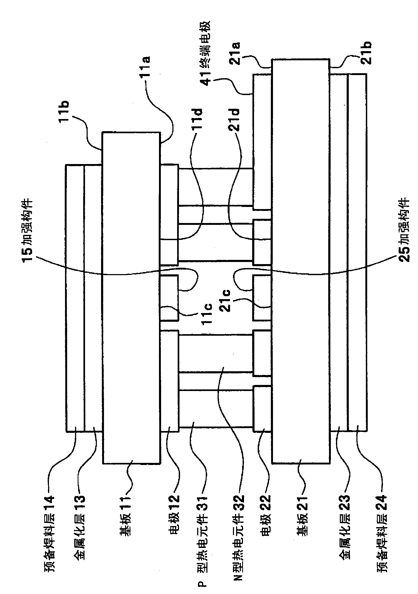
[0065] figure 1 The basic structure of the thermoelectric module of the first embodiment is shown.

[0066] figure 1 The thermoelectric assembly shown in 1 with Figure 18 The structural components of the conventional thermoelectric module 9 shown are the same, and the connection relationship of each structural component is also the same. The difference is the arrangement of the thermoelectric elements 31 , 32 or the electrodes 12 , 22 on the opposing surfaces 11 a , 21 a of the substrates 11 , 21 . Thus, in figure 1 In each structural part of the shown thermoelectric assembly 1 and Figure 18 In the shown thermoelectric module 9, the same components are assigned the same symbols, and the description of the structural components and connection relationship is omitted.

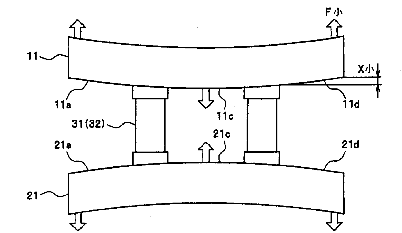
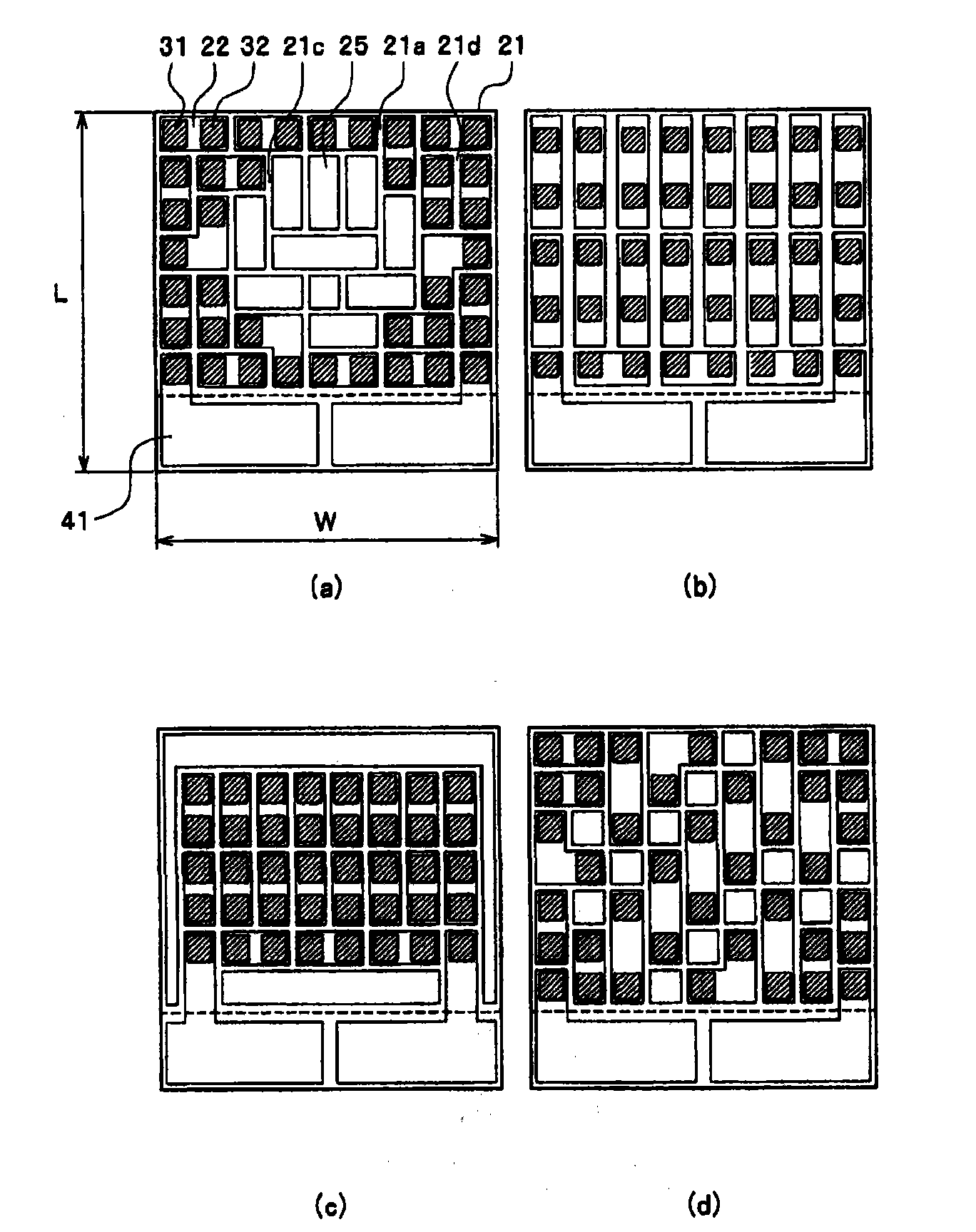
[0067] The thermoelectric elements 31 , 32 are arranged in areas 11 d , 21 d of the opposing surfaces 11 a , 21 a of the substrates 11 , 21 except for the central areas 11 c , 21 c. In the thermoelectric...

no. 2 approach

[0094] Figure 11 The basic structure of the thermoelectric module of the second embodiment is shown.

[0095] Figure 11 Thermoelectric assembly 2 shown with Figure 18 Most of the structural components of the conventional thermoelectric module 9 shown are the same, and the connection relationship and arrangement of each structural component are also the same. The difference is the thickness difference between the electrode and the metallization layer. Thus, in Figure 11 In each structural part of the shown thermoelectric assembly 2 and Figure 18 In the shown thermoelectric module 9, the same components are assigned the same symbols, and the description of the structural components and connection relationship is omitted.

[0096] Figure 11In the shown thermoelectric module 2 , the thickness of each electrode 12 , 22 is formed to be thicker than the thickness of the metallization layer 13 , 23 . The difference in thickness is such that the rate of change in resistance ...


PUM


Abstract

Thermoelectric elements are arranged with a high density in a peripheral region surrounding a center region or in an outer circumferential region of an opposing surface of a substrate instead of being arranged in the center region of the opposing surface. As compared to the case when the thermoelectric elements are arranged in the center of the opposing surface, when the thermoelectric elements are arranged in the region excluding the center region of the opposing surface, the thermoelectric element serving as a reference point of warp is positioned at an outer circumference side, i.e., the distance between the warp reference point and the outer circumference of the substrate becomes shorter. As the distance between the warp reference point and the outer circumference of the substrate becomes shorter, the displacement amount and the force of the warp caused at the outer circumference of the substrate become smaller. Moreover, when the thermoelectric elements are arranged with a high density, the force of each of the thermoelectric elements pulled by the substrate warp becomes smaller. Thus, by reducing the displacement amount and the force of the warp generated at the outer circumference of the substrate, it is possible to prevent a damage of the thermoelectric elements caused by the substrate warp.

Description

technical field [0001] The present invention relates to a thermoelectric component, which conducts heat from one substrate to another by utilizing the Peltier effect accompanying the energization of a series circuit composed of thermoelectric elements and electrodes, and particularly relates to a method for preventing The thermoelectric assembly is damaged by the substrate bending caused by the thermoelectric element damage. Background technique [0002] Use thermoelectric components as temperature adjustment devices for various equipment. Figure 18 is a diagram showing the structure of a typical thermoelectric module. The thermoelectric module 9 includes: two substrates 11, 21 facing each other; a plurality of electrodes 12, 22 formed on the opposing surfaces 11a, 21a of the substrates 11, 21; a plurality of P-type thermoelectric elements 31 and N-type thermoelectric elements. The elements 32 (hereinafter, simply referred to as "thermoelectric elements 31, 32") have one e...

Claims


Application Information

Patent Timeline
Patent Type & Authority Applications(China)
IPC IPC(8): H01L35/32
CPCH01L35/32H10N10/17
Inventor 小西明夫
Owner KELK LTD
Why Eureka
Try Eureka