Supercharge Your Innovation With Domain-Expert AI Agents!

Cone pulley structure of wire-drawing machine

A wire drawing machine and tower wheel technology, which is applied in the field of wire drawing machines, can solve the problems of failure of the tower wheel, inconvenient disassembly and exchange, and insufficient use of the tower wheel, and achieves simple installation, accurate positioning, and prevention of radial bouncing effect

Inactive Publication Date: 2010-10-27
上海励志机械有限公司
View PDF0 Cites 0 Cited by
  • Summary
  • Abstract
  • Description
  • Claims
  • Application Information

AI Technical Summary

Problems solved by technology

Such as carburizing, spraying and other methods, however, still cause the failure of the tower due to the local grooves, while most of the intact surface of the tower has not been fully used
[0004] The traditional structure of the tower pulley is installed on a straight shaft and positioned with a flat key. It is difficult to ensure the radial runout of the tower pulley after assembly, and it cannot meet the precision requirements for drawing ultra-fine precious metal wires. It is also extremely inconvenient to disassemble and replace.

Method used


Image

  • Cone pulley structure of wire-drawing machine
  • Cone pulley structure of wire-drawing machine
  • Cone pulley structure of wire-drawing machine

Examples


Embodiment Construction

[0015] In order to make the technical means, creative features, goals and effects achieved by the present invention easy to understand, the present invention will be further described below in conjunction with specific illustrations.
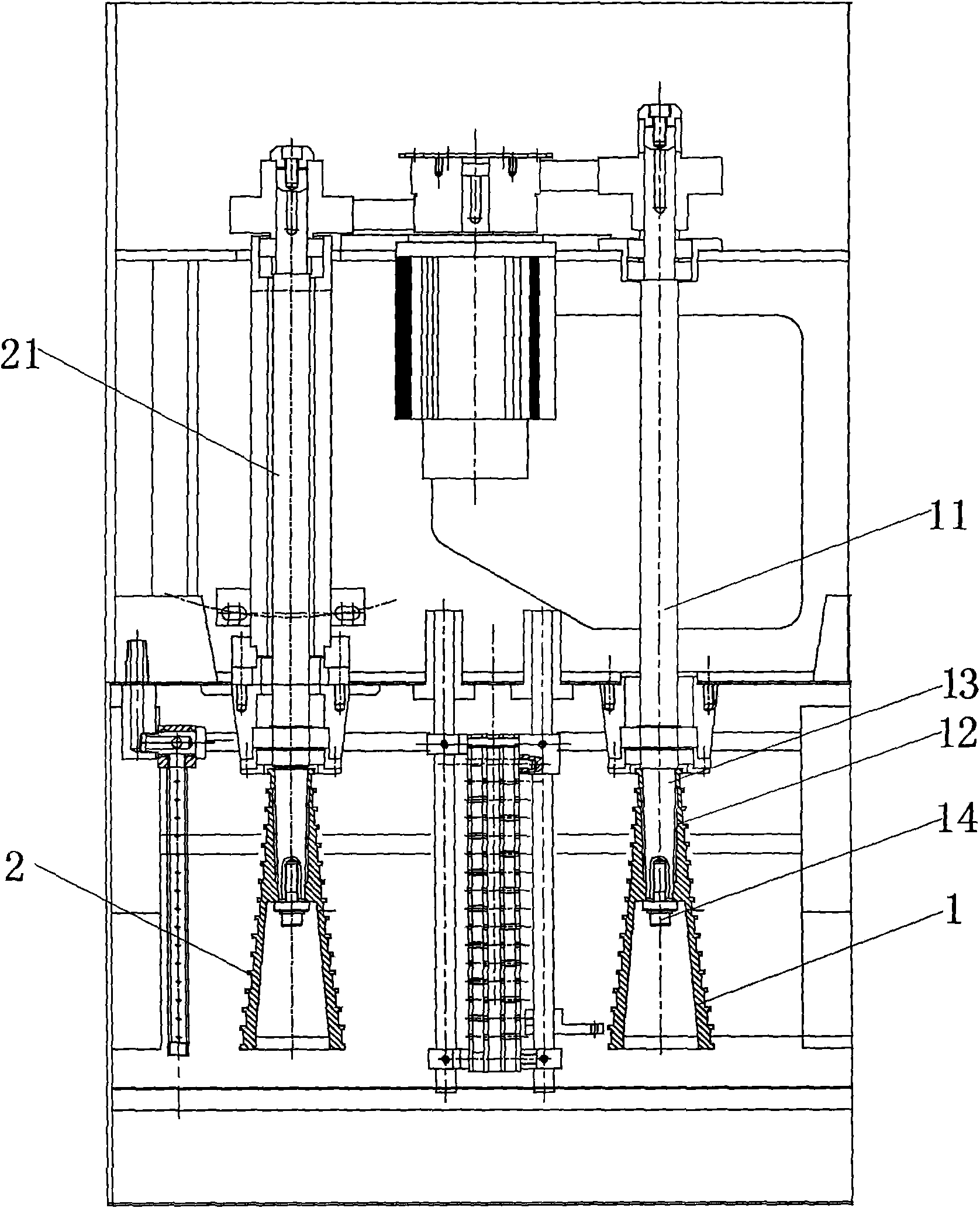
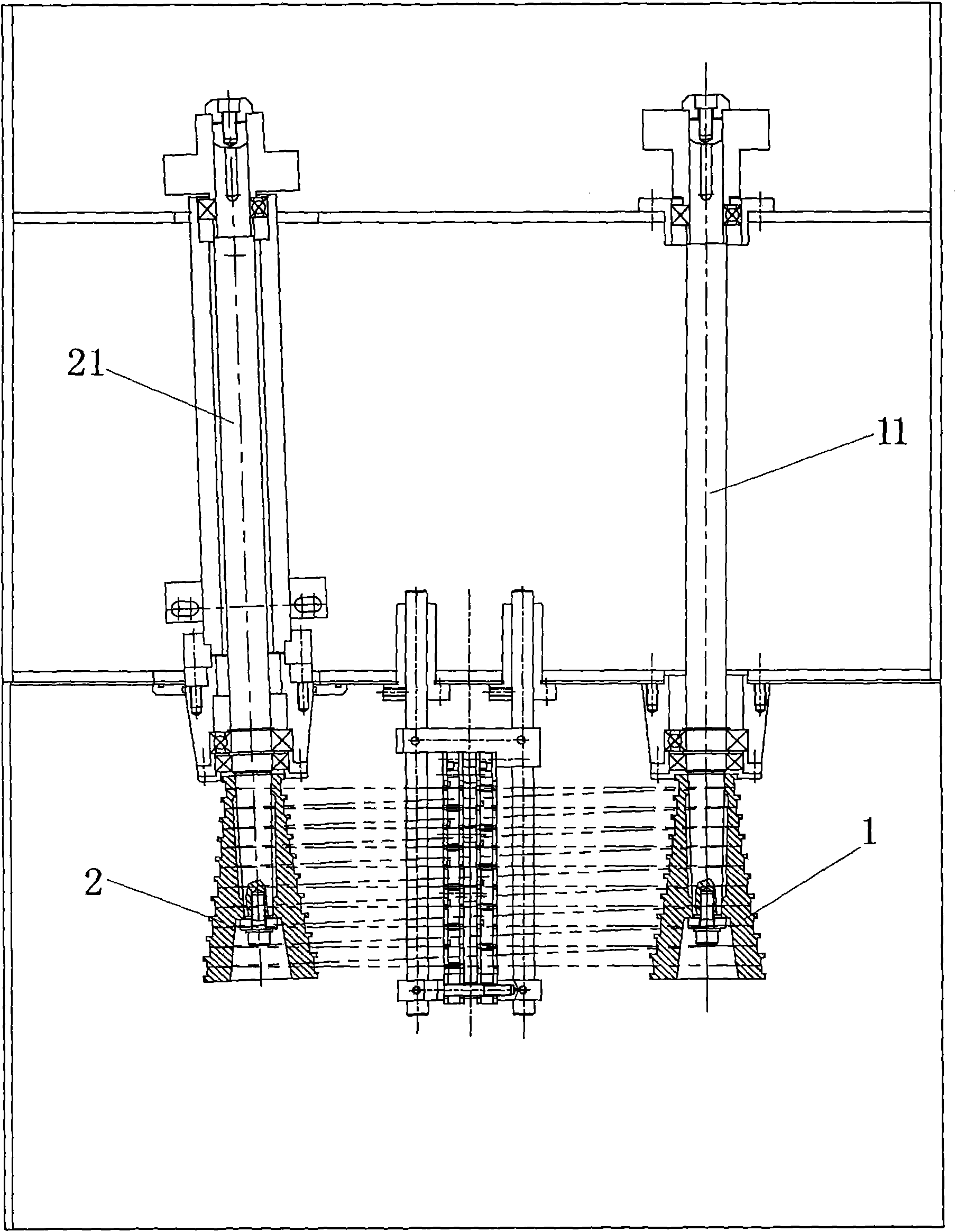
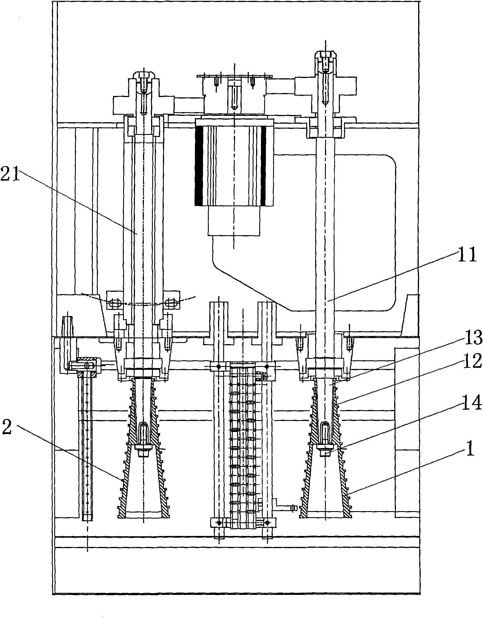
[0016] see figure 1

[0017] The figure is a schematic diagram of the local structure of the wire drawing machine. The tower wheel structure of the wire drawing machine has two tower wheels, one of which is the driving tower wheel 1, and the other is the driven tower wheel 2. The driving tower wheel 1 is driven by the tower wheel shaft 11. The driven tower wheel 2 is driven by the tower wheel shaft 21, and a mold base 3 is arranged between the two tower wheels. The mold base 3 moves in a direction parallel to the axis of the tower wheel. When grooving, the mold base 3 can move one position axially, thereby avoiding the place where the turret is grooved, so that the turret can continue to be used.

[0018] One end of the driving tower wheel 1 h...


PUM


Abstract

The invention relates to a cone pulley structure of a wire-drawing machine, which comprises two cone pulleys and die holders arranged inside the two cone pulleys, and is characterized in that the cone pulleys are multi-stage step-shaped cone pulleys; the die holders are provided with threading grooves matched with the cone pulleys; the die holders can move along the direction parallel to the axle lines of the cone pulleys; one end of each cone pulley is provided with a taper hole which is sheathed on a cone pulley shaft and is fixed by a bolt; and the axle line of one cone pulley is inclined relatively to that of the other cone pulley, and the angle of inclination is 2-5 degrees. The cone pulley structure is simple in installation and accurate in location, can effectively prevent the cone pulleys from jumping along the radial direction, and leads wires to be drawn along the straight line. When abrasion grooving is considered about, the positions of the die holders are only needed to be moved, and the grooving positions of the cone pulleys can be kept off.

Description

technical field [0001] The invention relates to the technical field of wire drawing machines, in particular to a tower pulley structure of a wire drawing machine. Background technique [0002] The tower pulley of the wire drawing machine is composed of a number of different direct coaxial cylindrical reels. During use, the motor drives the tower pulley to rotate through the transmission belt, and the active tower pulley rotates and draws through the traction force generated by the friction generated by the steel wire winding. Because the surface of each reel of the tower pulley is subjected to uneven friction by the steel wire for a long time, grooves will be formed. When the groove reaches a certain depth, it will easily cause "crimping" and break the wire. If you want to continue drawing, you must replace it with a new one. tower wheel. According to observations, the failure mode of the tower pulley is often to produce grooves in a local area of ​​the surface of each drum...

Claims


Application Information

Patent Timeline
Patent Type & Authority Applications(China)
IPC IPC(8): B21C1/14
Inventor 马晓东
Owner 上海励志机械有限公司
Features
  • R&D
  • Intellectual Property
  • Life Sciences
  • Materials
  • Tech Scout
  • Unparalleled Data Quality
  • Higher Quality Content
  • 60% Fewer Hallucinations
Learn More