
Eureka
For R&D, Eureka makes reading and utilizing patents & technical documents easy.
Eureka AIR
Designed for self-driven R&D workflows. Generate viable solutions, solve complex R&D challenges, empower your innovation with AI.

Eureka Materials
Designed for material experts only. Revolutionize your material R&D, from search, analyze, to developing new materials.

TechResearch
Generate reliable direction feasibility study reports for your R&D in just a few steps.

TechSeek
Discover and master advanced knowledge NOW. Basics, ideas, possibilities, all at once.

TechMind
As an expert in R&D Theories, TechMind can generates customized viable solutions instantly.

TechRisk
Analyze your overall solution with one click, know your potential R&D risks in advance.

TechMonitor
Get weekly tech updates, stay abreast of the latest tech innovations and key insights.
Demoulding mechanism of spiral undercut
A technology of demoulding mechanism and spiral, which is applied in the field of spiral barb demoulding mechanism, can solve the problems of troublesome mold assembly and complex structure, and achieve the effects of easy assembly, simple structure of demoulding mechanism and cost saving of mold assembly
- Summary
- Abstract
- Description
- Claims
- Application Information
AI Technical Summary
Problems solved by technology
Method used
Image

Examples
Embodiment Construction
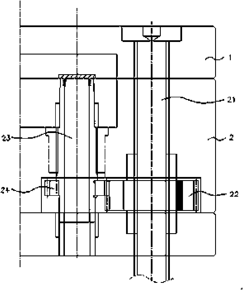
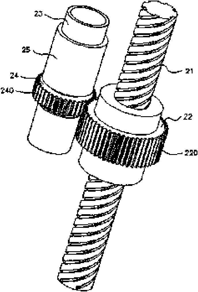
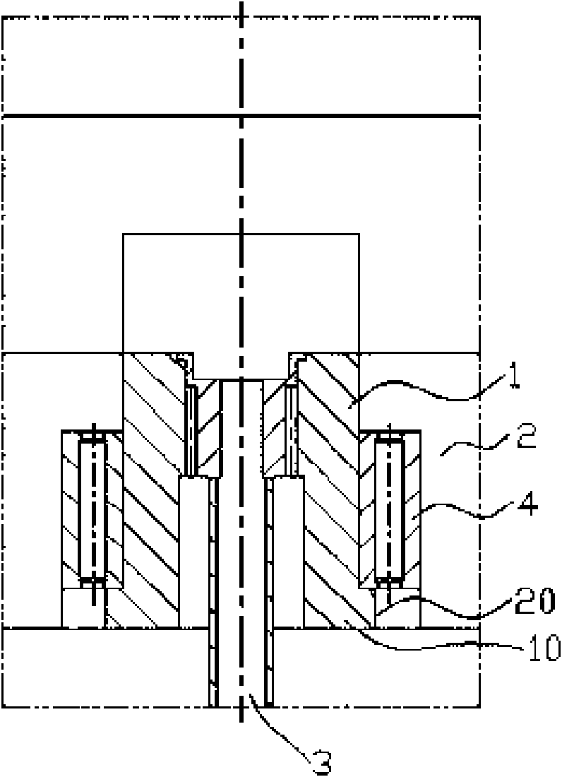
[0014] see image 3 The planar dissection structure schematic diagram of the demoulding mechanism of spiral barb of the present invention and Figure 4 As shown in the partial three-dimensional structure schematic diagram of the demoulding mechanism of the spiral barb of the present invention, the demoulding mechanism of the spiral barb is suitable for the production of spiral barb product molds with a helix angle greater than 45 degrees, which includes:
[0015] A rotary screw insert 1, the bottom of which extends a circle of convex portion 10 along its axial direction, and a groove 20 corresponding to the above-mentioned convex portion 10 is provided in the male template 2 of the above-mentioned mold, through the above-mentioned convex portion 10 and The cooperation of the above-mentioned groove 20 clamps the above-mentioned rotary screw inserter 1 in the male template 2 of the above-mentioned mould, and the rotary screw inserter 1 performs a horizontal rotation movement in ...
PUM
 Abstract
Description
Claims
Application Information
 - R&D Engineer
- R&D Manager
- IP Professional
- Industry Leading Data Capabilities
- Powerful AI technology
- Patent DNA Extraction
Browse by: Latest US Patents, China's latest patents, Technical Efficacy Thesaurus, Application Domain, Technology Topic, Popular Technical Reports.
© 2024 PatSnap. All rights reserved.Legal|Privacy policy|Modern Slavery Act Transparency Statement|Sitemap|About US| Contact US: help@patsnap.com