Crank type underwater robot ejection device

An underwater robot and ejection device technology, which is applied to underwater operation equipment, transportation and packaging, ships, etc., can solve the problems of fixed range, difficult waterproofing, complex structure, etc., and achieve the effect of strengthening mutual cooperation and improving work efficiency.

Inactive Publication Date: 2010-10-27
PEKING UNIV
View PDF7 Cites 11 Cited by
  • Summary
  • Abstract
  • Description
  • Claims
  • Application Information

AI Technical Summary

Problems solved by technology

The cost of this method is relatively high, and it is more difficult to implement
There are also mechanical methods, such as using springs as power, but the general structure is more complicated ...

Method used


Image

  • Crank type underwater robot ejection device
  • Crank type underwater robot ejection device
  • Crank type underwater robot ejection device

Examples


Embodiment Construction

[0017] The present invention will be further described through the embodiments below in conjunction with the accompanying drawings.

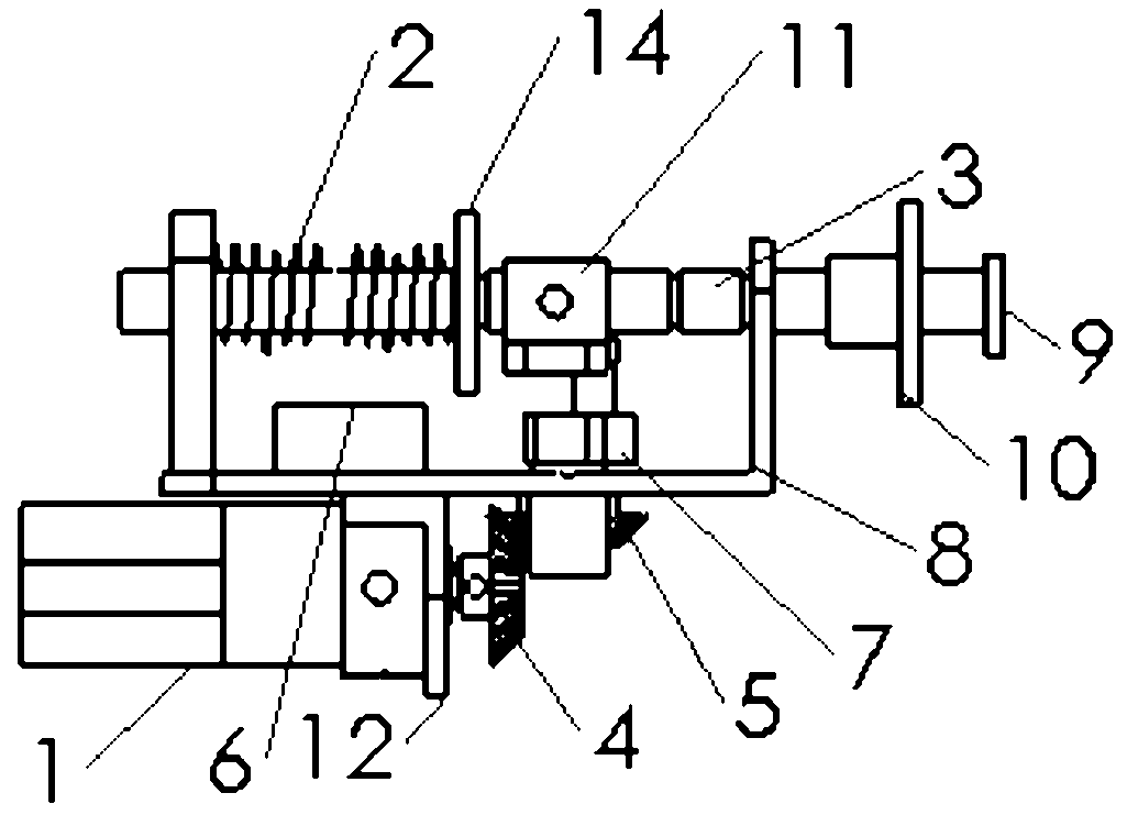
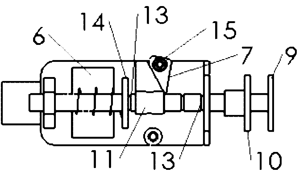
[0018] as attached figure 1 , attached figure 2 As shown, the device is installed on the inner wall of the underwater robot cavity and can be controlled by the core board system (control board) of the underwater robot. board to determine the current status. If it is in the disconnected state, the control board sends instructions to the motor 1 to make it rotate until the limiter switch is closed, and the state at this time is called the initial position. If it is in the closed state, then keep the current state and wait for the instruction.

[0019] When the device was in the initial position, that is, when the limiter 6 switch was in the closed state, the crank 7 was in the limit position. The control board sends ejection commands to the motor 1 according to the task requirements. The rotation of the motor 1 drives the bevel gear 4, and t...


PUM


Abstract

The invention discloses a crank mechanism-based underwater robot ejection device, and belongs to the field of amphibious robot preparation. The device adopts a motor to drive a bevel gear so as to drive a crank mechanism, uses the crank mechanism to compress a spring and releases the compression energy of the spring at a proper position so that a spring force is acted on an object to fulfill the purpose of ejection. The space is effectively utilized by adopting a bevel gear driving mechanism, and the volume of the ejection device is greatly reduced. The device can realize self-locking function and continuous ejection, and can solve practical masks of object carrying, transfer, multi-robot cooperation and the like of a small scale robot. The device is used for ejecting a lightweight object to reach an ideal position, and can be used for reinforcing mutual cooperation among multiple robots. At the same time, the device improves the work efficiency of a machine, saves the energy and improves the object transfer accuracy.

Description

technical field [0001] The invention belongs to the field of amphibious robot preparation, and in particular relates to an underwater robot ejection device based on a crank mechanism. Background technique [0002] At present, there are many types of ejection devices used by robots, such as rail-type launchers, drop-in launchers, suspension devices, connection launchers, and the like. A common method is to use pneumatics, but this device is generally larger in size and suitable for larger wheeled robots. There are also electromagnetic methods, using solenoids, electromagnets, etc. as power. The cost of this method is relatively high, and it is more difficult to implement. There are also mechanical methods, such as using springs as power, but the general structure is relatively complicated and the range is fixed. And because the robot is underwater, the waterproofing of the device with relative moving parts in the underwater interior and exterior compartments is a current t...

Claims


Application Information

Patent Timeline
IPC IPC(8): B63C11/52
Inventor 罗法毅谢广明尹新彦王龙
Owner PEKING UNIV
Why Eureka
Try Eureka