Packaging method of LED (light-emitting diode) flexible lamp strip
An encapsulation method and a technology for flexible light bars, which are applied to lighting devices, lighting device parts, light sources, etc., can solve the problems of high production cost, complex process, low production efficiency, etc., and achieve low equipment maintenance costs and simple production process. , the effect of high production efficiency
- Summary
- Abstract
- Description
- Claims
- Application Information
AI Technical Summary
Problems solved by technology
Method used
Image

Examples
Embodiment Construction
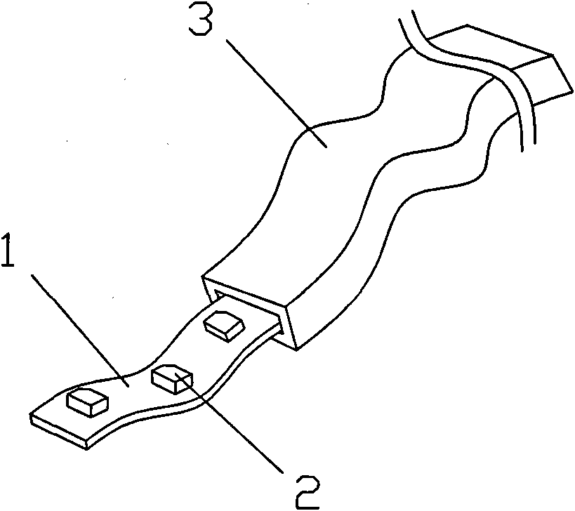
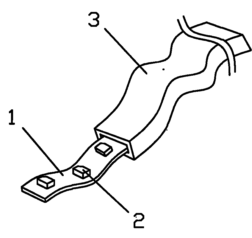
[0019] refer to figure 1 , the present invention a kind of LED flexible light bar packaging method, comprises the following steps:
[0020] 1) Provide a flexible circuit board 1;
[0021] 2) Provide several in-line or SMD LED light sources 2;
[0022] 3) Welding the above-mentioned LED light source 2 on the above-mentioned flexible circuit board 1 by means of reflow soldering or wave soldering;
[0023] 4) Provide a strip-shaped flexible shell 3;
[0024] 5) importing the above-mentioned flexible circuit board 1 welded with the LED light source into the above-mentioned flexible housing 3;
[0025] 6) Inject glue into the flexible shell 3 and let it dry and solidify.
[0026] Above-mentioned technical scheme also can have following improvement scheme: described step 5) comprises the following steps:
[0027] ①Through the steel wire through the flexible shell, the two ends of the steel wire are exposed outside the flexible shell;
[0028] ②Connect the end of the flexible c...
PUM
 Abstract
Description
Claims
Application Information