
Backlight module and liquid crystal display device

A technology of backlight module and fixing device, which is applied to lighting devices, fixed lighting devices, lighting auxiliary devices, etc., achieves the effects of convenient and quick assembly, increased light use efficiency, and increased heat dissipation efficiency

Inactive Publication Date: 2010-10-27
AU OPTRONICS CORP
View PDF0 Cites 21 Cited by
  • Summary
  • Abstract
  • Description
  • Claims
  • Application Information

AI Technical Summary

Problems solved by technology

The light guide plate is set in the back frame

Method used


Image

  • Backlight module and liquid crystal display device
  • Backlight module and liquid crystal display device
  • Backlight module and liquid crystal display device

Examples


Embodiment Construction

[0025] In order to have a further understanding of the purpose, structure, features, and functions of the present invention, the following detailed descriptions are provided in conjunction with the embodiments.

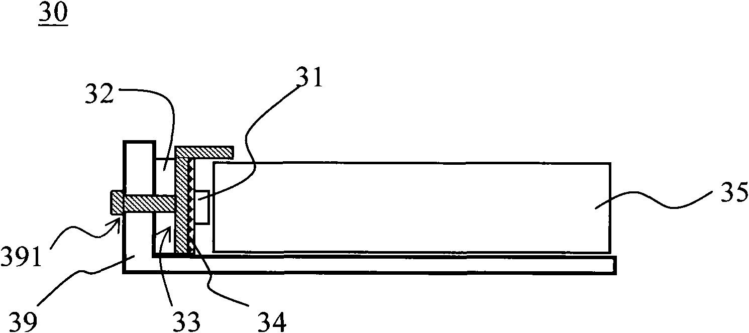
[0026] See image 3 , image 3 It is a schematic cross-sectional view of an edge-lit LED backlight module 30 according to an embodiment of the present invention. The backlight module 30 includes a back frame 39 , a light guide plate 35 , a fixing device 33 and an LED light bar, wherein the LED light bar includes an LED light source 31 and a circuit board 32 . Please refer to Figure 5 , Figure 5 It is a structural schematic diagram of an LED light bar according to an embodiment of the present invention. The light guide plate 35 and the LED light strips are disposed in the back frame 39 . The LED light sources 31 are arranged at intervals on the circuit board 32 , and the light-emitting surfaces of the LED light sources 31 face the light guide plate 35 . The cir...


PUM


Abstract

The invention relates to a backlight module and a liquid crystal display device. The backlight module comprises a back frame, a light guide board, LED light sources, a circuit board and a fixing device, wherein, the side edge of the back frame is provided with a first clamping slot; the light guide board is arranged in the back frame; the LED light sources are arranged on the circuit board at intervals; the light-emitting surfaces of the LED light sources exactly face the light guide board; the circuit board is provided with a second clamping slot; the fixing device comprises a substrate with placing holes; the substrate is provided with a first surface and a second surface; the first surface is provided with a clamping part; the second surface faces the light guide board; the clamping part fixes the circuit board on the side edge of the back frame through the second clamping slot and the first clamping slot; and the LED light sources are arranged in the placing holes. Through the invention, the assembly of LED light strips is convenient and fast, and the assembled LED light strips and the back frame are in tight contact, thereby improving the heat dissipation efficiency.

Description

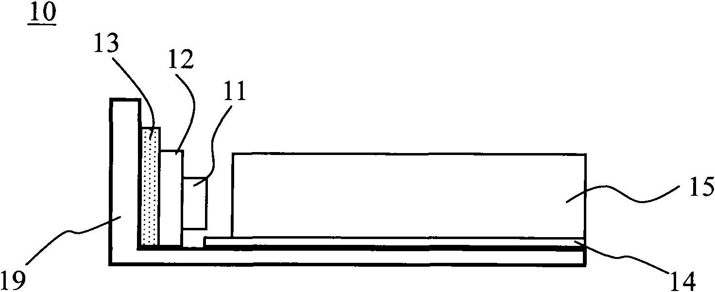
technical field [0001] The present invention relates to a backlight module and a liquid crystal display device, in particular to a backlight module and a liquid crystal display device with an LED light source fixing device that is easy to assemble and has good heat dissipation. Background technique [0002] At present, side-lit backlight modules configured with point light sources such as LEDs have been widely used in various liquid crystal display devices. See figure 1 , figure 1 It is a schematic cross-sectional view of a traditional edge-lit LED backlight module 10 fixed by double-sided adhesive tape. The light guide plate 15 is arranged in the back frame 19, the bottom surface of the light guide plate 15 can be provided with a reflective sheet or a reflective layer 14, and an LED point light source 11 is arranged at one end of the light guide plate 15, and the LED point light source 11 is arranged on the circuit board 12, and the circuit board 12 It is fixed on the ba...

Claims


Application Information

Patent Timeline
Patent Type & Authority Applications(China)
IPC IPC(8): F21S8/00F21V21/00F21V8/00F21V17/10F21V19/00G02F1/13357G02F1/133F21Y105/00F21Y101/02
Inventor 郑川河林信吾黄国正
Owner AU OPTRONICS CORP
Learn More