Virtual MIMO (Multiple Input Multiple Output) relay transmission method and system based on cluster user cooperation

A transmission method and user technology, applied in diversity/multi-antenna systems, space transmit diversity, electrical components, etc., can solve the problem of increasing construction costs, reducing system capacity and spectral efficiency, user terminal uplink transmission capacity and transmission reliability. Insufficient guarantee and other problems, to achieve the effect of high channel utilization and improved reliability

Inactive Publication Date: 2010-10-27
CIVIL AVIATION UNIV OF CHINA
View PDF3 Cites 21 Cited by
  • Summary
  • Abstract
  • Description
  • Claims
  • Application Information

AI Technical Summary

Problems solved by technology

But at the same time, there are the following disadvantages: due to the extra time-frequency resources occupied by the link between the user terminal and the relay station, the system capacity and spectrum efficiency are greatly reduced; the spatial multiplexing and diversity gain provided by the multi-antenna system cannot be used, making the uplink transmission of the user terminal The capacity and transmission reliability cannot be fully guaranteed; additional relay station equipment needs to be arranged in the existing mobile communication system, which greatly increases the construction cost
[0013] and figure 1 Compared with the given single-antenna relay system based on DFT-S-OFDM, the virtual MIMO relay transmission system based on D-STBC cod

Method used


Image

  • Virtual MIMO (Multiple Input Multiple Output) relay transmission method and system based on cluster user cooperation
  • Virtual MIMO (Multiple Input Multiple Output) relay transmission method and system based on cluster user cooperation
  • Virtual MIMO (Multiple Input Multiple Output) relay transmission method and system based on cluster user cooperation

Examples


Embodiment Construction

[0044] The virtual MIMO relay transmission method and system based on cluster user cooperation of the present invention will be described in detail below with reference to the embodiments and the accompanying drawings.

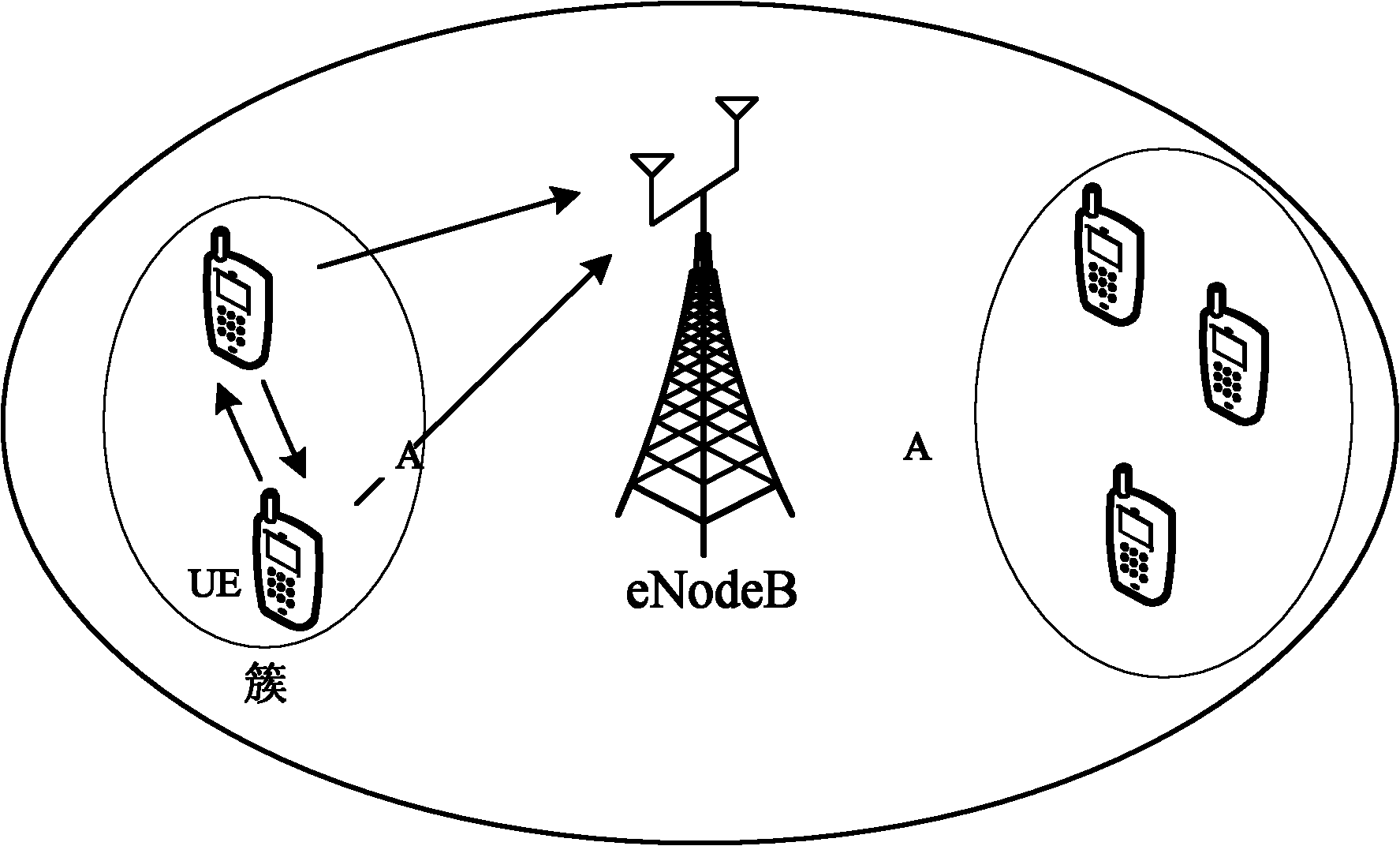
[0045] In the virtual MIMO relay transmission method based on cluster user cooperation of the present invention, the virtual MIMO transmission technology is used between the user terminal and the base station, and several spatially adjacent user terminals are divided into a cluster according to the distribution of the user terminals in the cell (cluster), the cell is composed of multiple clusters; the distance between the user terminals in the same cluster is relatively close, and the channel transmission characteristics are good, the channel between the user terminals in the cluster is modeled as a Rice channel; while the distance between the user terminals in the cluster and the base station is relatively long , the channel between the user terminal and the b...


PUM


Abstract

The invention discloses virtual MIMO (Multiple Input Multiple Output) relay transmission method and system based on cluster user cooperation. The method comprises the following steps of: dividing a plurality of user terminals adjacent in space into a cluster according to the distribution condition of the user terminals in cells by taking a virtual MIMO transmission technology between each user terminal and a base station, wherein each cell includes a plurality of clusters; modeling a channel between every two user terminals in the cluster to form a Ricean channel; modeling a channel between each user terminal and the base station to form a multipath reyleigh fading channel; and enabling two user terminals in the same cluster to mutually cooperate so as to finish the information transmission from each user terminal to the base station within three time slots. The system comprises the plurality of user terminals and the base station communicated with the plurality of user terminals, wherein clusters formed by the plurality of adjacent user terminals are mutually cooperated to finish the information transmission from each user terminal to the base station within three time slots. The invention remarkably improves the reliability of link transmission of the user terminals in a cellular mobile communication system by sufficiently utilizing the space diversity gain provided by the cooperation of users and also obtains higher utilization ratio of the channel.

Description

technical field [0001] The invention relates to a relay transmission system. In particular, it relates to a virtual MIMO relay transmission method and system based on cluster user cooperation. Background technique [0002] In order to meet users' needs for broadband mobile communications, 3GPP launched the LTE research project in 2004. The uplink of the LTE system adopts the single carrier frequency division multiple access (SC-FDMA) access scheme, and the downlink adopts the OFDMA transmission scheme. After four years of work, 3GPP completed the standardization of the LTE Rel 8 system in December 2008. [0003] In order to further meet the goals determined by the IMT-advanced plan proposed by the International Telecommunication Union ITU, 3GPP launched the LTE-advanced research plan in 2008. The goal of the plan is to enhance the basic LTE system on the basis of the basic specifications determined by LTE Rel 8. And achieve the following goals: system transmission bandwid...

Claims


Application Information

Patent Timeline
IPC IPC(8): H04B7/06H04B7/08H04L1/06H04W88/04
Inventor 刘海涛杜超
Owner CIVIL AVIATION UNIV OF CHINA
Why Eureka
Try Eureka