Quick switch method and system under protected mode in passive optical network and optical network unit

An optical network unit and passive optical network technology, applied in the field of communication, can solve the problems of prolonging the switching time, unable to meet the user's requirements for rapid recovery of network faults, affecting the ONU and OLT to quickly restore normal communication, etc., to reduce switching. Time, reduce the amount of data interaction, and quickly restore the effect of communication

Active Publication Date: 2010-10-27
ZTE CORP
View PDF5 Cites 9 Cited by
  • Summary
  • Abstract
  • Description
  • Claims
  • Application Information

AI Technical Summary

Problems solved by technology

The problems that cause like this include: (1) each ONU all completes above-mentioned series of state transitions and OLT needs to bear a large amount of message transmission work; For example, in a 125us Gigabit-Capable Passive Optical Network (GPON) GPON transmission conversion downlink frame (GPON Transmission Conversion, GTC for short) there is not enough capacity to store physical layer operation management and maintenance (Physical Layer Operation Administration and Maintenance, referred to as PLOAM) message to support 32 ONUs to complete the aforementioned state transition process at the same time, so most ONUs need to wait for the message, prolong the switching time, affect the fast recovery of normal communication between ONU and OLT, and make ONU and OLT resume normal work The basic time-consuming is more than 100 milliseconds, which cannot meet the user's requirements for fast recovery from network failures

Method used


Image

  • Quick switch method and system under protected mode in passive optical network and optical network unit
  • Quick switch method and system under protected mode in passive optical network and optical network unit
  • Quick switch method and system under protected mode in passive optical network and optical network unit

Examples


specific Embodiment 1

[0065] Specific embodiment one, such as Figure 7 As shown, the ONU directly transitions from state O2 to state O5 during the switching process. Specifically include the following steps:

[0066] Step 1, the optical network unit stores the identification of each protection path corresponding to the optical port of the optical line terminal and the establishment parameters of the protection path;

[0067]The protection path establishment parameters corresponding to each protection path include at least the following information:

[0068] preamble bit type;

[0069] Delimiter parameter (Delimiter);

[0070] ONU sends optical power level parameters;

[0071] Equalization delay signal EqD (Equalization Delay).

[0072] The protection channel establishment parameters corresponding to each protection channel may also include an ONU ID.

[0073] Step 2: After the service path for data communication between the ONU and the OLT is invalid, the OLT activates an available optical p...

specific Embodiment 2

[0076] Specific embodiment two, such as Figure 8 As shown, the ONU directly transitions from state O3 to state O5 during the switching process. Specifically include the following steps:

[0077] Step 1, the optical network unit stores the identification of each protection path corresponding to the optical port of the optical line terminal and the establishment parameters of the protection path;

[0078] The protection path establishment parameters related to each protection path include at least the following information:

[0079] Equalization delay signal EqD (Equalization Delay).

[0080] The protection channel establishment parameters corresponding to each protection channel may also include an ONU ID.

[0081] Step 2: After the service path for data communication between the ONU and the OLT becomes invalid, the OLT activates an available optical port and completes synchronization with the ONU through the target path corresponding to the optical port, and the ONU starts...

specific Embodiment 3

[0084] Specific embodiment three, such as Figure 9 As shown, the ONU directly transitions from state O4 to state O5 during the switching process. Specifically include the following steps:

[0085] Step 1, the optical network unit stores the identification of each protection path corresponding to the optical port of the optical line terminal and the establishment parameters of the protection path;

[0086] The protection path establishment parameters related to each protection path include at least the following information:

[0087] Equalization delay signal EqD (Equalization Delay).

[0088] Step 2: After the service path for data communication between the ONU and the OLT becomes invalid, the OLT activates an available optical port and completes synchronization with the ONU through the target path corresponding to the optical port, and the ONU starts from the The optical line terminal receives the uplink overhead parameters and enters the ranging state (O4); the process o...


PUM


Abstract

The invention discloses a quick switch method and system under the protected mode in a passive optical network and an optical network unit. The method comprises the following steps: the optical network unit stores the identifier of a protected path corresponding to the optical port of an optical line terminal and a protected path building parameter; after a service path for data communication between the optical network unit and the optical line terminal is invalid, the optical line terminal starts an available optical port and synchronizes with the optical network unit via a path corresponding to the optical port, namely a destination path; the optical line terminal sends a quick switch indication message to the optical network unit and carries the identifier of the destination path, the optical network unit extracts the protected path building parameter of the destination path according to the identifier and completes the subsequent building process with the destination path of the optical line terminal by using the protected path building parameter to enter into the operation state. The invention can reduce the switching time of the optical network unit under the protected mode, reduce the data exchange amount in switching and improve the time for the optical network unit to restore normal work to millisecond level.

Description

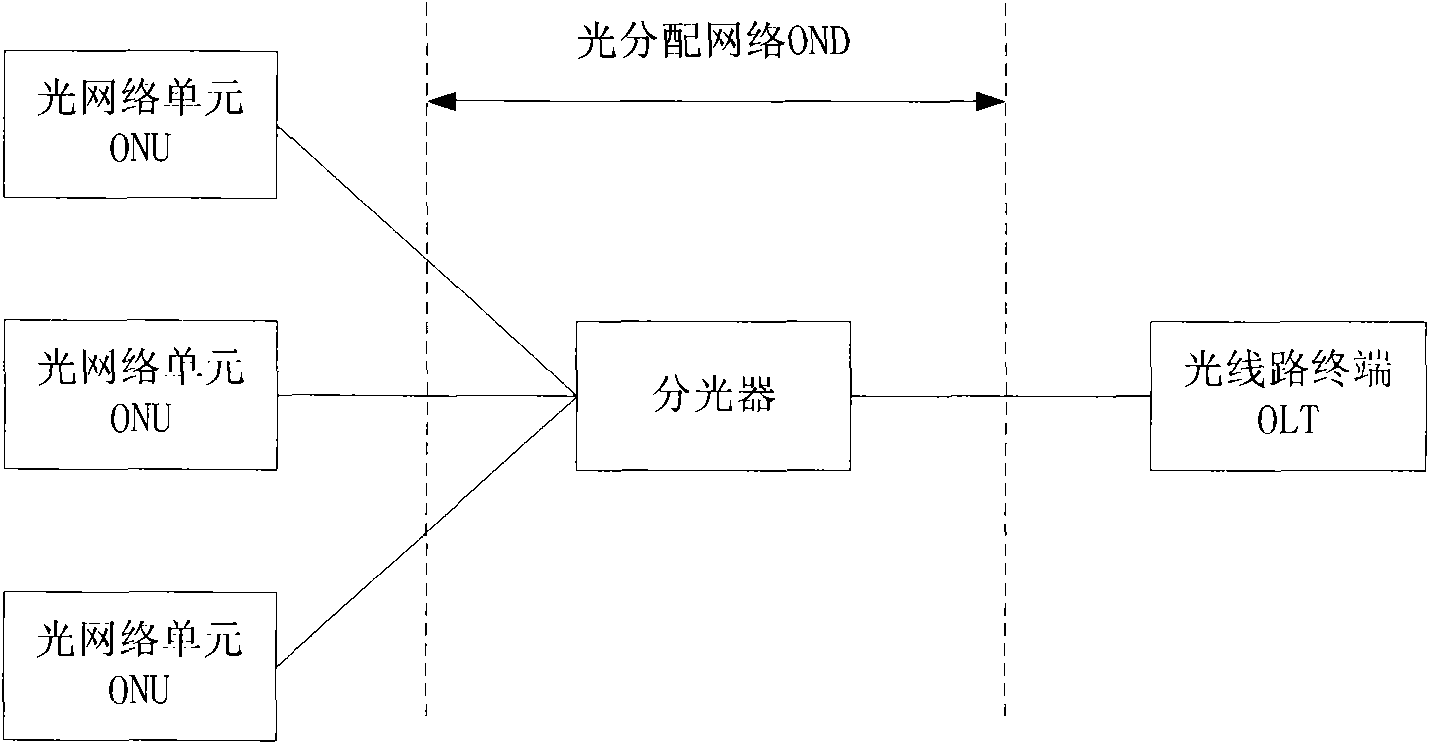
technical field [0001] The present invention relates to the communication field, in particular to a fast switching method, system and optical network unit (Optical Network Unit, ONU) in a protection mode in a passive optical network (Passive Optical Network, PON for short). Background technique [0002] With the development of broadband access technology, operators are gradually accepting and deploying an optical access network (OAN) to provide users with faster speed and higher quality services. [0003] A point-to-multipoint optical fiber access technology is adopted in the passive optical network. Such as figure 1 As shown, the passive optical network includes an optical line terminal (Optical Line Terminal, OLT for short), an optical network unit (ONU), and an optical distribution network (Optical Distribution Network, ODN for short). The Optical Distribution Network (ODN) is a point-to-multipoint structure. An Optical Line Terminal (OLT) is connected to multiple Optic...

Claims


Application Information

Patent Timeline
Patent Type & Authority Applications(China)
IPC IPC(8): H04Q11/00H04B10/08H04B10/032
Inventor 张德智张伟良
Owner ZTE CORP
Why Eureka
Try Eureka