Constant-speed transmission shaft with telescopic middle shaft

A constant-speed transmission, intermediate shaft technology, applied in couplings, elastic couplings, mechanical equipment, etc., can solve the problem of poor intermediate shaft slippage, large circumferential transmission clearance, and bending moment at the gearbox end. Large and other problems, to achieve the effect of increased expansion and contraction, large axial space, and smooth transmission

Active Publication Date: 2010-11-03
常州超宇机械制造有限公司
View PDF0 Cites 9 Cited by
  • Summary
  • Abstract
  • Description
  • Claims
  • Application Information

AI Technical Summary

Problems solved by technology

[0008] 2) The circumferential transmission gap is large
[0010] 3) The shock resistance is poor, and the gearbox end is greatly affected by the bending moment force
[0011] Due to the large clearance of the center-moving constant velocity universal joint, during the use of the transmission shaft, the intermediate shaft is close to the end of the moving end, which is prone to vibration or vibration; The force is uniform, but the force-bearing surface is not perpendicular to the output axis of the gearbox. The distance from each point of force to the gearbox end is different, and the bending moment on the gearbox end is also different. Each force point will have a different impact on the gearbox end. A bending moment difference is ge

Method used


Image

  • Constant-speed transmission shaft with telescopic middle shaft
  • Constant-speed transmission shaft with telescopic middle shaft
  • Constant-speed transmission shaft with telescopic middle shaft

Examples


Embodiment 1

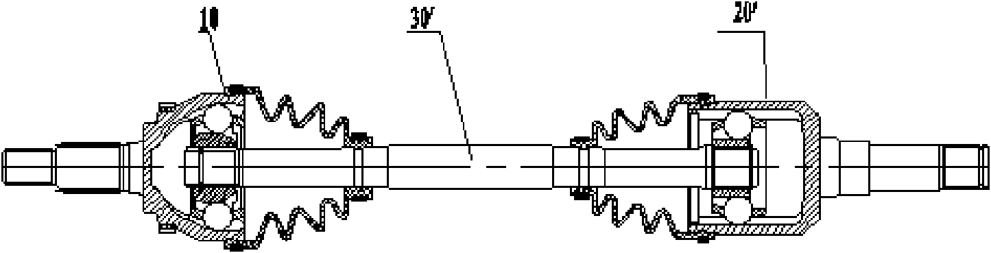
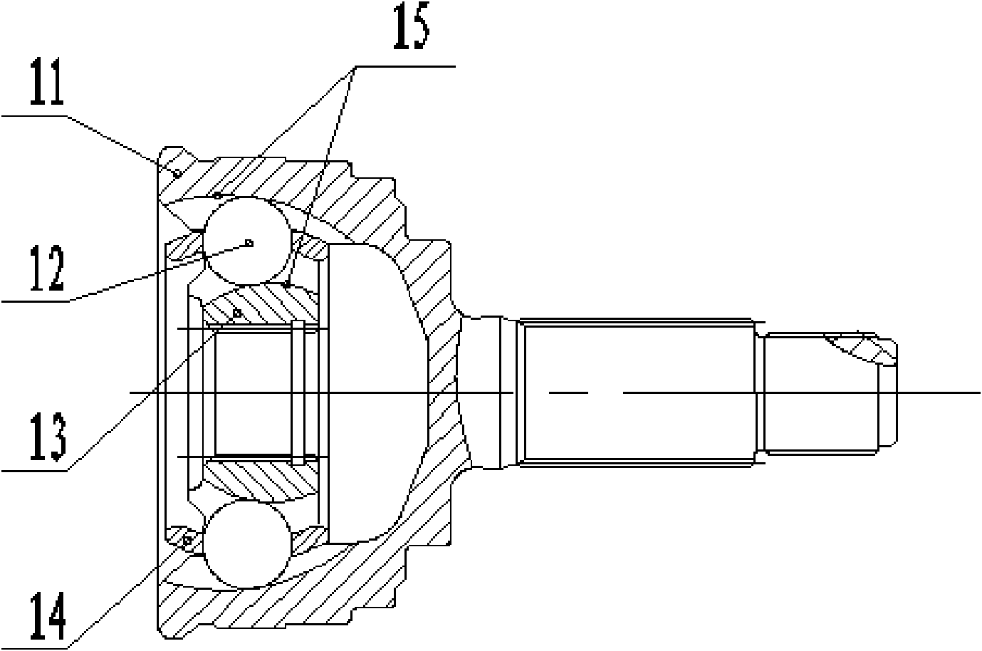
[0055] See Figure 6 , Figure 6-1 and Figure 6-2 , the transmission shaft of the present invention has a center-fixed constant velocity universal joint 10 at the drive wheel end, a center-fixed constant velocity universal joint 20 at the gearbox end, and an intermediate shaft 30. The intermediate shaft includes an intermediate shaft sleeve 31, an intermediate shaft core 33, a retaining Frame 34 and rolling element 32. In this embodiment, rolling element 32 is a steel ball. The mating surface of the intermediate bushing and the intermediate shaft core is a circumferential surface. Corresponding channels for accommodating steel balls are respectively provided. The shape can be a double arc or a single arc, and the cage is used to fix the relative position of the steel balls to ensure the rolling of the steel balls and the transmission of torque.

[0056] Such as Figure 6-1 and Figure 6-2 As shown, the outer diameter of the intermediate shaft sleeve is D1, the outer diame...

Embodiment 2

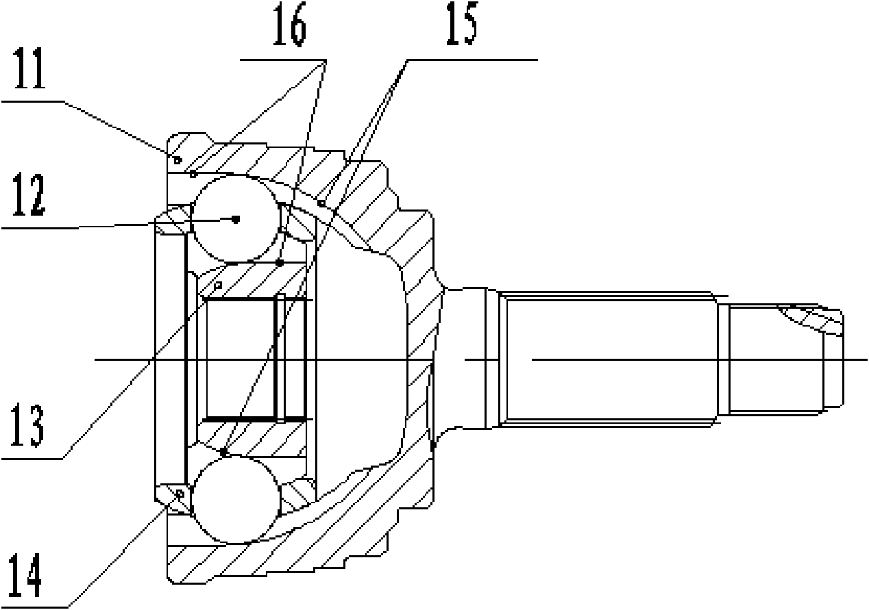
[0068] The intermediate shaft of the present invention can also adopt another structure, that is, the inner cavity of the intermediate shaft sleeve 31 and the outer shape of the intermediate shaft core 33 are regular polygons, the rolling element 32 adopts a needle roller type, and the corresponding cage 34 is also a regular polygon. The transmission of torque is completed by the corners of the cage.

[0069] The intermediate shaft sleeve, intermediate shaft core and needle roller are installed with a small interference fit, and the outer surface of the intermediate shaft core and the inner surface of the intermediate shaft sleeve are lubricated with grease, which can also ensure the telescopic function of the intermediate shaft, and because the contact surface of the needle roller is large , Strong wear resistance during use.


PUM


Abstract

The invention relates to front and rear wheel transmission shafts of a car or other mechanical transmission equipment, in particular to a middle shaft structure of a front wheel driving shaft for a car, aiming to provide a constant-speed transmission shaft with a telescopic middle shaft with favorable lubricating condition and excellent sliding performance. The constant-speed transmission shaft with a telescopic middle shaft is provided with a constant-speed universal joint of a driving wheel end center fixing type, a constant-speed universal joint of a gearbox end center fixing type and a middle shaft, wherein the middle shaft comprises a middle shaft sleeve, a middle shaft core, a retainer and rolling pieces, the middle shaft sleeve is sleeved on the middle shaft core, mutually matched grooves are respectively and evenly distributed on the periphery of the inner surface of the middle shaft sleeve and the periphery of the outer surface of the middle shaft core, the rolling pieces are arranged in the grooves between the middle shaft sleeve and the middle shaft core, and the mutual relative positions of the rolling pieces are fixed by the retainer. The middle shaft of the invention comprises the middle shaft sleeve, the middle shaft core, the retainer and the rolling pieces and has excellent transmission performance.

Description

technical field [0001] The invention relates to front and rear wheel transmission shafts of automobiles or other mechanical transmission equipment, in particular to an intermediate shaft structure of front wheel drive shafts for automobiles. Background technique [0002] The design of automobile transmission shaft has been explored and improved for a long time, and various types of transmission structures exist in actual vehicle design and production to varying degrees. [0003] Such as figure 1 As shown, the constant velocity transmission shafts of a large number of automobile driving wheels are generally composed of a center fixed constant velocity universal joint 10 at the driving wheel end, a center moving constant velocity universal joint 20' at the transmission end and an intermediate shaft 30'. The center-fixed constant velocity universal joint 10 has two structures, which are BJ type and UJ type. Such as figure 2 , diagram 2-1 As shown, the BJ-type centrally fi...

Claims


Application Information

Patent Timeline
IPC IPC(8): F16D3/223F16D3/84
Inventor 王玉南
Owner 常州超宇机械制造有限公司
Why Eureka
Try Eureka