Rotating mechanism of bearing platform for detection

A technology of a rotating mechanism and a bearing platform, applied in the direction of the casing of the measuring device, etc., can solve problems such as affecting accuracy and deformation

Inactive Publication Date: 2010-11-03
MICROELECTRONICS TECH INC
View PDF2 Cites 4 Cited by
  • Summary
  • Abstract
  • Description
  • Claims
  • Application Information

AI Technical Summary

Problems solved by technology

[0009] However, the disadvantage of the rotary mechanism 2 is the same as figure 1 The positioning system 1 is the same, when the motor 20 is driven, the screw 21 rotates so that the connecting rod 22 moves, the screw 21 not only generates a force applied horizontally to the direction of the screw 21, but also generates a force not horizontal to the direction of the screw 21, Easy to deform and affect accuracy

Method used


Image

  • Rotating mechanism of bearing platform for detection
  • Rotating mechanism of bearing platform for detection
  • Rotating mechanism of bearing platform for detection

Examples


Embodiment Construction

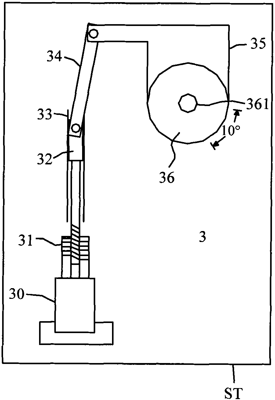
[0048] see image 3 , which is a schematic top view of a first preferred embodiment of the rotation mechanism of the detection carrier proposed by the present invention. exist image 3 Among them, the rotating mechanism 3 is composed of a motor 30, a screw rod 31 that is controlled by the motor 30 to rotate, a slider 32 that is fixedly connected to the screw rod 31 at one end and slides on a slide rail 33, and a connecting rod 34 that is pivotally connected to the slider 32 at one end. , and a crank 35, and the rotating mechanism 3 is fixed on the base ST. Wherein, one end of the crank 35 is pivotally connected to the other end of the connecting rod 34 , and the other end is fixedly connected to the bearing platform 36 .

[0049] Wherein, when the motor 30 operates, the screw rod 31 rotates to push the slide block 32 to slide on the slide rail 33, so that the connecting rod 34 pivots relative to the slide block 32, so that the crank 35 and the bearing table 36 move simultane...


PUM


Abstract

The invention provides a rotating mechanism of a bearing platform for detection, and a base platform is fixedly arranged on the rotating mechanism; the rotating mechanism comprises a motor which is controlled by a rotational screw rod, a sliding block of which one end is fixedly connected to the screw rod and slides on a sliding rail, a connecting rod of which one end is pivoted to the sliding block, and a crank handle; one end of the crank handle is pivoted to the other end of the connecting rod, the other end of the crank handle is fixedly connected to the bearing platform; wherein when the motor acts on, the screw rod rotates to push the sliding block to slide on the sliding rail, so as to lead the connecting rod to be rotated relative to the sliding rod in a pivoting way and cause the crank handle and the bearing platform to rotate with an angle at the same time relative to the base platform.

Description

technical field [0001] The invention relates to a rotating mechanism, in particular to a rotating mechanism applied to a carrying platform for detection. Background technique [0002] In testing machines for LED, semiconductor and other testing fields, the carrying table is used to carry wafers to be tested such as LEDs and semiconductors. By rotating the carrying table at an angle, the probes passing through the testing machine will touch the wafer to be tested. The contact pad of the object, and then test the electrical properties of the object to be tested on the wafer. [0003] Generally, a commonly used testing machine uses a belt on the side of the loading platform, and the belt is driven by a motor to make the loading platform rotate at an angle. However, since the carrier must maintain this angle, the use of the belt will cause gap density problems, which will affect the rotation accuracy of the carrier, and finally lead to poor electrical testing of the wafer DUT. ...

Claims


Application Information

Patent Timeline
Patent Type & Authority Applications(China)
IPC IPC(8): G01R1/04
Inventor 杨天德
Owner MICROELECTRONICS TECH INC
Why Eureka
Try Eureka