Container connector

A technology for containers and connectors, which is applied in packaging, cargo, ship accessories, etc., and can solve the problems of container unloading operations and troubles

Inactive Publication Date: 2010-11-03
NIPPON YOOSEN KABUSHIKI KAISHA +2
View PDF1 Cites 9 Cited by
  • Summary
  • Abstract
  • Description
  • Claims
  • Application Information

AI Technical Summary

Problems solved by technology

Therefore, with this structure, an extremely strong container fastening force can be exerted, but conversely, since the cone cannot be removed from the corner casting or the socket without manually rotating the cone, the unloading work of the container is troublesome.

Method used


Image

  • Container connector
  • Container connector
  • Container connector

Examples


no. 1 example

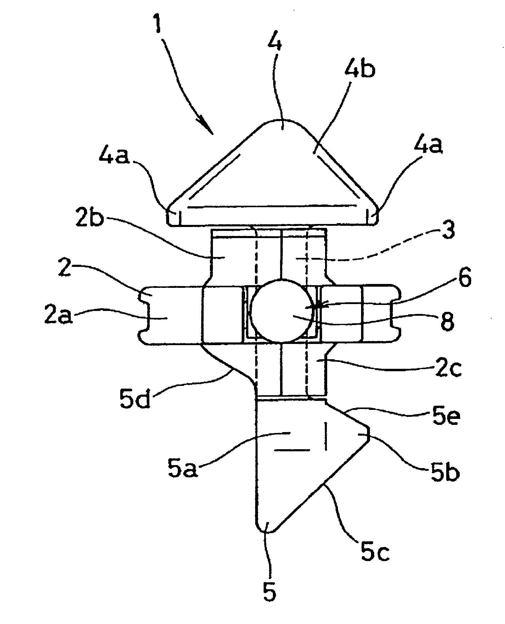
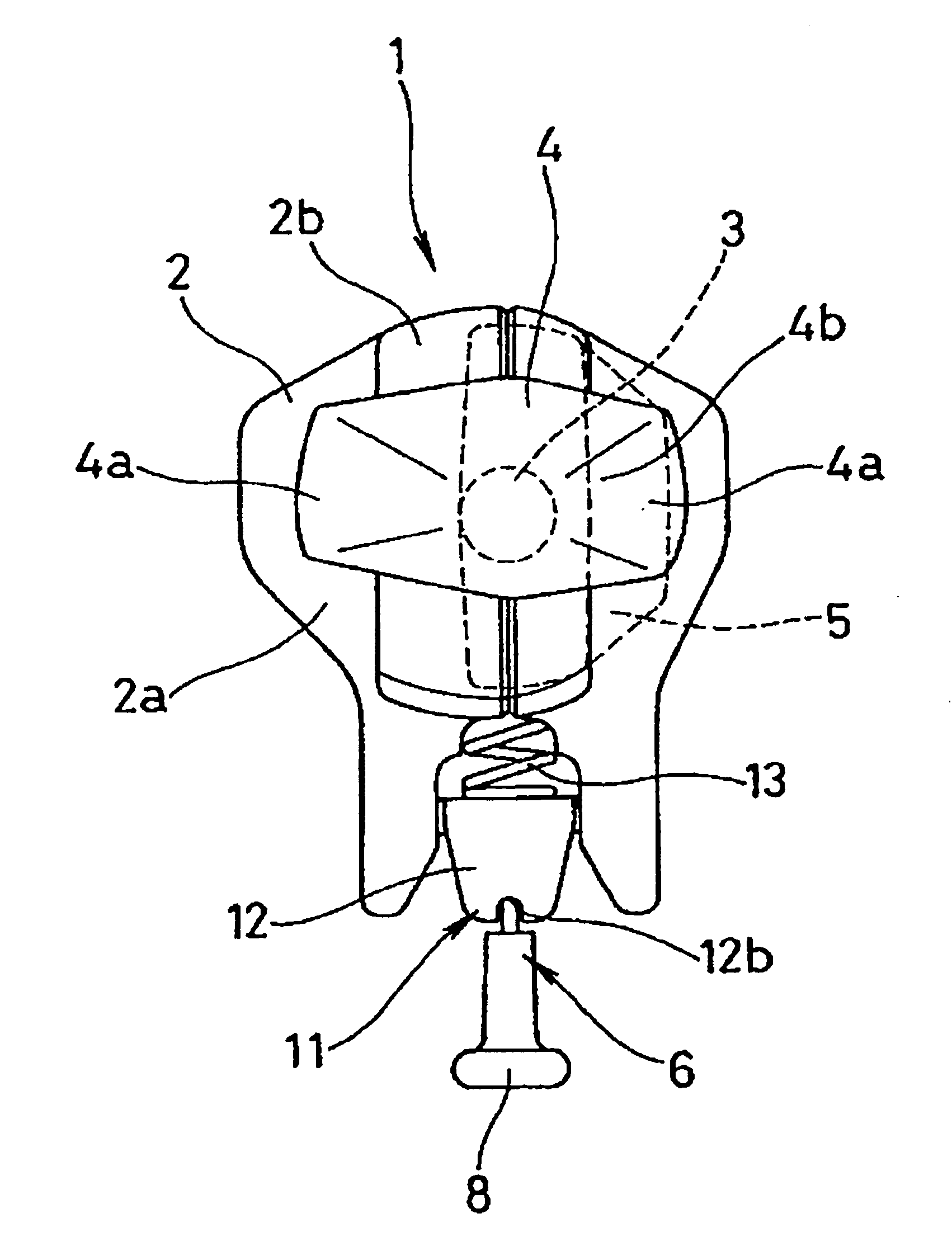
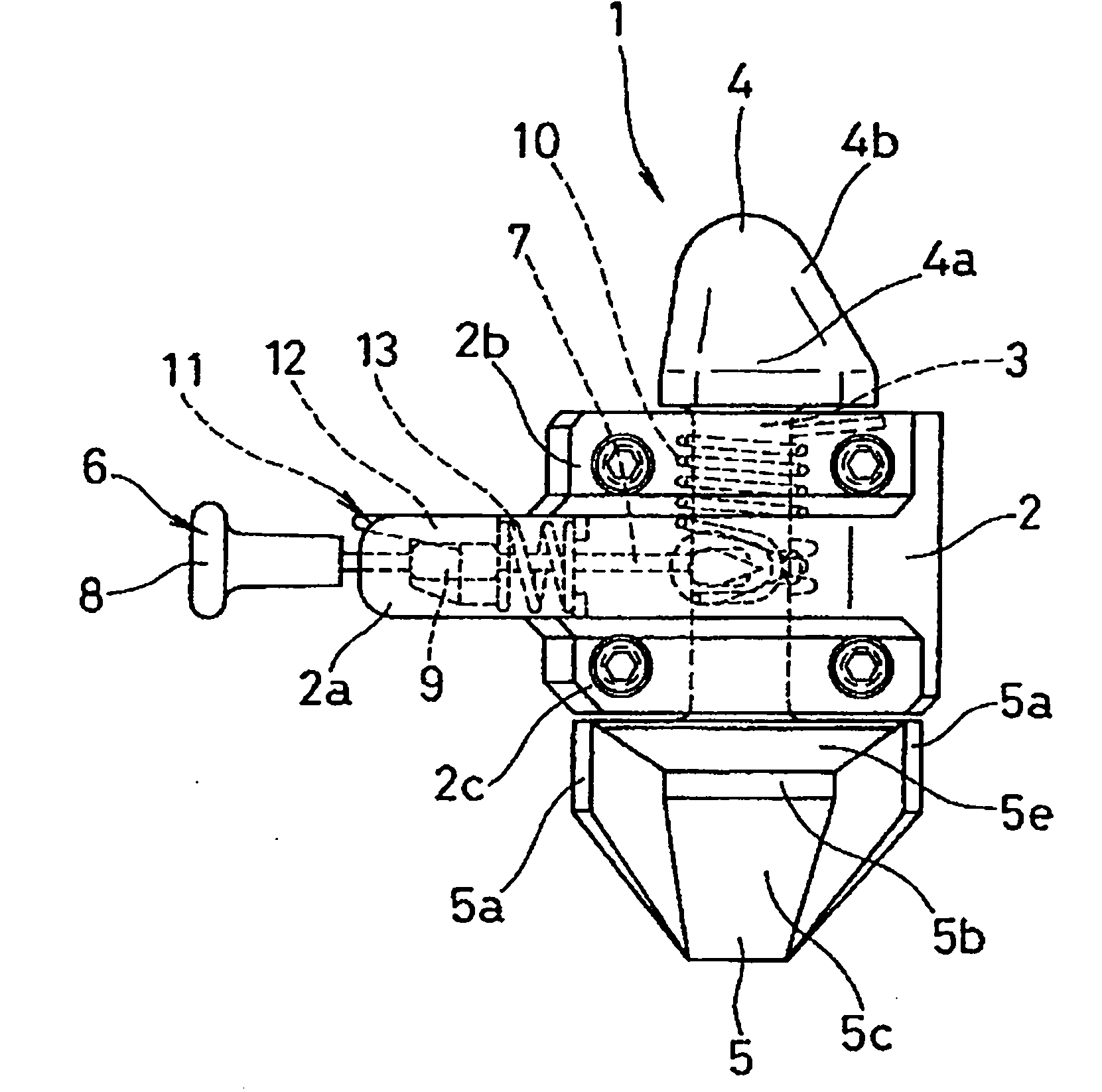
[0095] respectively expressed as: figure 1 is a front view of the connector for the container according to the first embodiment of the present invention, figure 2 is a top view, image 3 is the right side view, Figure 4 is the left view, Figure 5 is a plan view. And, respectively expressed as: Figure 6 to Figure 8 is an explanatory diagram of the rotation position of the upper and lower cones, Figure 9 to Figure 12 It is an explanatory diagram of the operating state of the connector. According to its function and structure, this connecting piece is called container fastening twist lock (twist lock). In addition, the description in the "Example" column below also describes the case of loading and unloading a plurality of containers. Therefore, in the case of securing the container to the deck, in the following descriptions, replace "upper container" with "container", and "the lower corner casting of the upper container" with "the lower corner casting of the containe...

no. 2 example

[0129] In the above-mentioned first embodiment, the initial position of the shaft 3 is that the rotation engagement structure of the upper cone 4 is at the engagement position, the rotation engagement structure of the lower cone 5 is at the engagement release position, and the second engagement Construct the first rotation stop position capable of action ( Figure 6 ), but not limited thereto, the initial motion position of the shaft 3 can also be the second rotation stop position where the rotation engagement structure of the upper side cone 4 and the rotation engagement structure of the lower side cone 5 are all located at the engagement position, for example .

[0130] From this point of view, in this second embodiment, as Figure 15 As shown, when the initial position of the shaft 3 is that the rotation engagement structure of the upper cone 4 and the rotation engagement structure of the lower cone 5 are both located at the second rotation stop position of the engagement ...

no. 3 example

[0134] and, in Figure 17 as well as Figure 18 In the third embodiment shown, the angle θ at which the longitudinal directions of the upper and lower cones 4, 5 intersect in the planar shape 2 It is set to about 110 degrees (based on the long side direction of the upper side cone 4, the long side direction of the lower side cone 5 is displaced about 110 degrees toward the shaft rotation direction (rotating to the left in the figure)), according to the application Inventor's verification, the plane shapes of the upper and lower cones 4, 5 are Figure 17 as well as Figure 18 In the case shown in , when the angle is set in this way, the engagement area (contact area at the time of engagement) of the cones 4, 5 with respect to the corner castings 22, 25 can be set to the maximum. , be suitable for the angle that the longitudinal direction intersects in the planar shape of upper and lower cones 4,5 to be set at 100-120 degree (the longitudinal direction of upper side cone 4 is...


PUM


Abstract

A container connector having cones at upper and lower parts of a shaft of the connector. The lower cone can be detached from an upper corner casting of a lower container or a socket on a deck board without manually rotating the lower cone. The construction enhances workability of load discharging and provides sufficient fastening force required in different situations. To achieve the above, the lower cone has a rotation engagement structure and a non-rotatable second engagement structure. The rotation engagement structure allows the lower cone to engage with an inner edge of an engagement hole when the lower cone is in inserted into the upper corner casting or the socket and rotated from a disengagement position to an engagement position. The second engagement structure allows a projection-like engagement section, which is arranged on a side face of the lower cone, to engage with the inner edge of the engagement hole even if the lower cone is not rotated when it is inserted into the upper corner casting or the socket.

Description

technical field [0001] The invention relates to a connecting piece for a container related to container loading fastening technology. The connector of the present invention is used when loading and unloading a plurality of containers, or when fixing containers to the deck of a ship, and the like. Background technique [0002] Conventionally, as disclosed in the following patent document 1, etc., there is known a container connector having an upper cone and a lower cone, wherein the upper cone engages with a lower corner provided on the lower surface of an upper container. Casting (in case of loading multiple containers up and down) or lower corner casting (in case of fixing the container on the deck of the ship) installed on the bottom of the container, and the lower cone is engaged on the upper surface of the lower container The upper corner casting (in the case of loading multiple containers up and down) or the socket installed on the deck of the ship (in the case of fixi...

Claims


Application Information

Patent Timeline
Patent Type & Authority Applications(China)
IPC IPC(8): B65D88/12B63B25/00B65D90/00
CPCB63B25/004B65D90/0013
Inventor 藤田裕安藤英幸铃木久雄早间和春小田泰宽
Owner NIPPON YOOSEN KABUSHIKI KAISHA
Why Eureka
Try Eureka