Check patentability & draft patents in minutes with Patsnap Eureka AI!

Track type dredger installation structure

A technology of installation structure and dredger, which is applied in the field of mining machinery, can solve the problems of not being durable, heavy hydraulic device load, and shortened service life, etc.

Active Publication Date: 2010-11-10
PUYANG YALI MACHINERY MFG
View PDF4 Cites 0 Cited by
  • Summary
  • Abstract
  • Description
  • Claims
  • Application Information

AI Technical Summary

Problems solved by technology

[0002] In my country's electric power, coal, chemical industry, metallurgy, building materials and other industries, the silos containing materials are generally square cones and cones with a large upper part and a smaller lower part. Many materials have relatively high humidity or viscosity, which is easy to block the silo. These silos are generally equipped with dredgers. The dredgers include vertically arranged pull rods. There are several scrapers on the pull rods. There are limit snap rings outside the pull rods. The snap rings are welded to the pre-set pre-embedded On the part, when the tie rod moves up and down, the whole tie rod directly rubs against the wall of the silo, and the friction force is very large, which increases the wear degree of the tie rod; the existing tie rod is made of channel steel, which has limited bending resistance and is not very durable; and because The transverse lengths of all scrapers are equal, the hydraulic power is large when starting, it is not easy to start, and when the scrapers move downward, the resistance is very large, the load of the hydraulic device is large, and the power consumption is also increased, which virtually reduces the oil cylinder, The service life of oil pumps, electromagnetic reversing valves, motors, electronic components and other components

Method used


Image

  • Track type dredger installation structure
  • Track type dredger installation structure
  • Track type dredger installation structure

Examples


Embodiment Construction

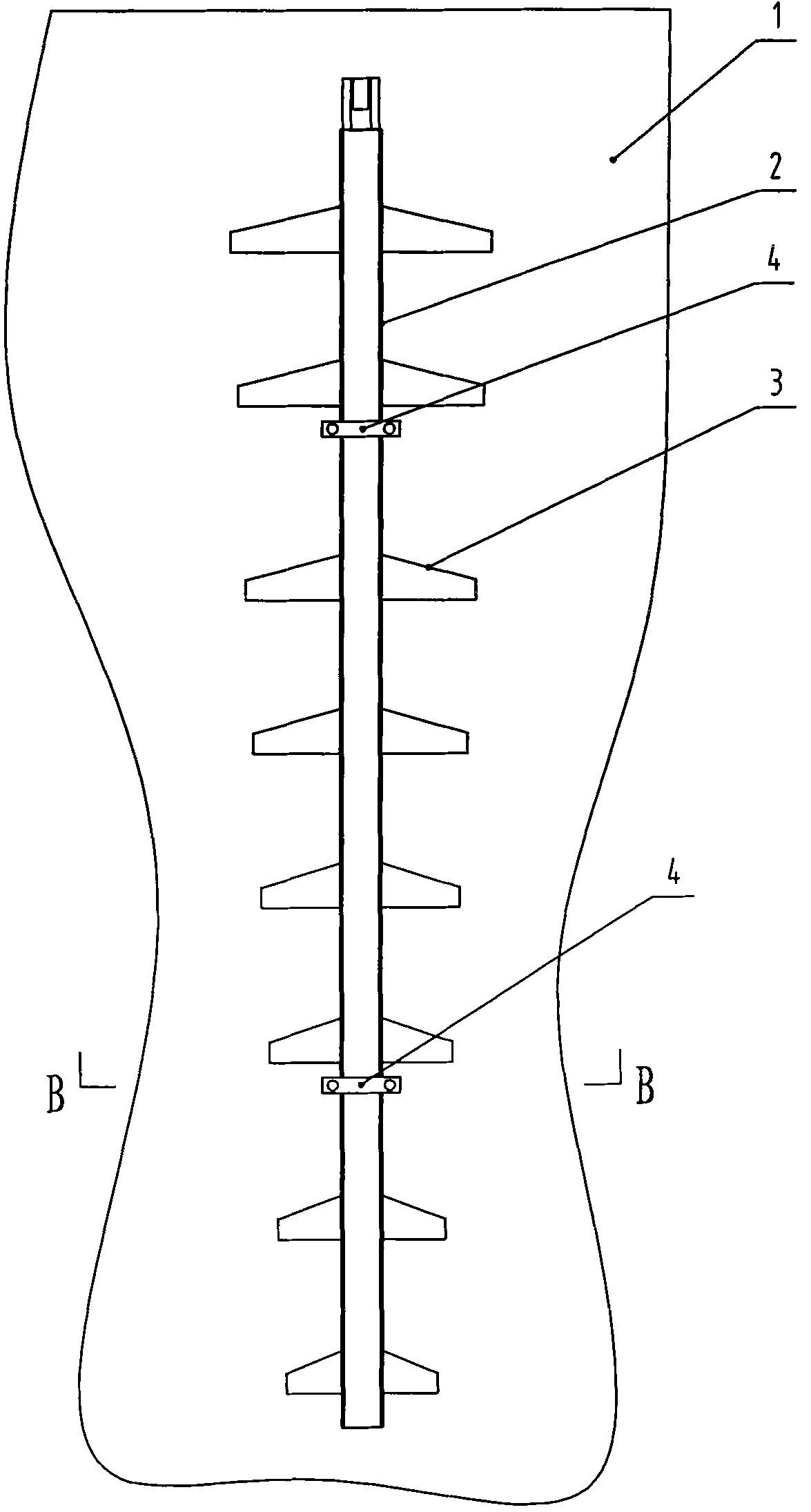
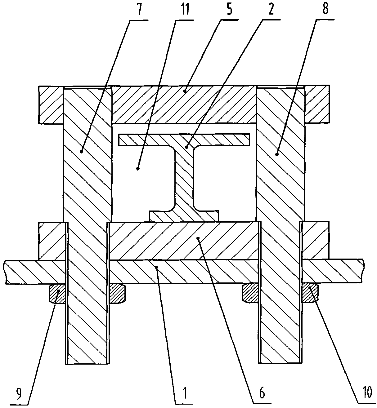
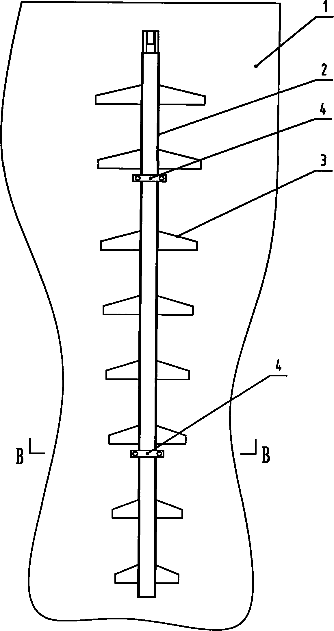
[0011] Such as figure 1 and figure 2 As shown, the installation structure of the track-type dredger of the present invention includes a silo 1, a tie rod 2 is vertically arranged in the hopper 1, and a plurality of scrapers 3 are arranged horizontally on the pull bar 2 axially, and each scraper 3 is about the pull rod. The axis of 2 is symmetrical, the length of each scraper 3 in the horizontal direction is gradually shortened from top to bottom, the vertical distance between two adjacent scrapers 3 is equal, and the connection line between the ends of the same side of each scraper for a straight line. The inner wall of the silo 1 is provided with a limiting device 4, the limiting device 4 includes a clamping plate 5, a clamping plate 6, a bolt 7 and a bolt 8, the clamping plate 5 and the clamping plate 6 are arranged in parallel, the bolt 7 and the bolt 8 are arranged in parallel, and the clamping plate 5 Set vertically with the bolt 7, the same end of the bolt 7 and the b...


PUM


Abstract

The invention discloses a track type dredger installation structure, which comprises a bin which is internally and vertically provided with a pull rod, a plurality of scraping sheets are arranged horizontally and axially on the pull rod, each scraping sheet is symmetrical relative to an axis of the pull rod, the inner wall of the bin is provided with a limit device which comprises two parallel chuck plates and two parallel bolts, the two chuck plates and the two bolts are vertically arranged, one ends of the two bolts are both in threaded connection with one chuck plate, the other ends of the two bolts are both in fastening connection with the other chuck plate and the bin through nuts, and the pull rod is inserted in a square hold formed by the two chuck plates and the two bolts. In the invention, the pull rod is in contact with the chuck plates and has no more friction generated with the inner wall of the bin, thereby the friction force is reduced and the pull rod is difficult to abrade and can move up and down in a more flexible and labor-saving way; and in addition, the detachable installation structure has reasonable design and is easy to disassemble and maintain.

Description

technical field [0001] The invention belongs to the technical field of mining machinery, and in particular relates to an installation structure of a track-type dredge. Background technique [0002] In my country's electric power, coal, chemical industry, metallurgy, building materials and other industries, the silos containing materials are generally square cones and cones with a large upper part and a smaller lower part. Many materials have relatively high humidity or viscosity, which is easy to block the silo. These silos are generally equipped with dredgers. The dredgers include vertically arranged pull rods. There are several scrapers on the pull rods. There are limit snap rings outside the pull rods. The snap rings are welded to the pre-set pre-embedded On the part, when the tie rod moves up and down, the whole tie rod directly rubs against the wall of the silo, and the friction force is very large, which increases the wear degree of the tie rod; the existing tie rod is m...

Claims


Application Information

Patent Timeline
IPC IPC(8): B65D88/64
Inventor 贾卫中王振怀武新宽冯柳磊王自达郭银柱杨彦雨
Owner PUYANG YALI MACHINERY MFG
Features
  • R&D
  • Intellectual Property
  • Life Sciences
  • Materials
  • Tech Scout
  • Unparalleled Data Quality
  • Higher Quality Content
  • 60% Fewer Hallucinations
Learn More