Flat-head tower crane

A tower crane and flat head technology, applied in cranes and other directions, can solve the problems of large design cost, large calculation result error, large calculation amount, etc., and achieve low requirements for installation equipment, less overall installation time, and high space utilization. Effect

Inactive Publication Date: 2010-11-10
HARBIN HUATUO METAL STRUCTURE
View PDF6 Cites 13 Cited by
  • Summary
  • Abstract
  • Description
  • Claims
  • Application Information

AI Technical Summary

Problems solved by technology

Because the ordinary tower crane has a tie rod, the jib can only be removed from the jib section other than the lifting point, it is difficult to disassemble the jib section arbitrarily in the air, and the jib section of the ordinary tower crane must be assembled and disassembled as a whole. Under limited conditions, if the site cannot meet the overall installation of the jib section, or the truck crane cannot approach, the installation of ordinary tower cranes will be difficult to complete
When the position of the luffing trolley of the ordinary tower crane is different, the stress on the same part of the boom will be obviously different. Fatigue damage or even fracture and weld cracking of the boom will greatly affect the service life and safety of the steel structure of the boom
Because the tower top and tie rods of ordinary tower cranes need to undergo complex calculations, and at this time there are many calculation conditions, the mechanical model is very complicated, the amount of calculation is large, the error of the calculation results is large, and a large design cost is required

Method used


Image

  • Flat-head tower crane
  • Flat-head tower crane

Examples


Embodiment 1

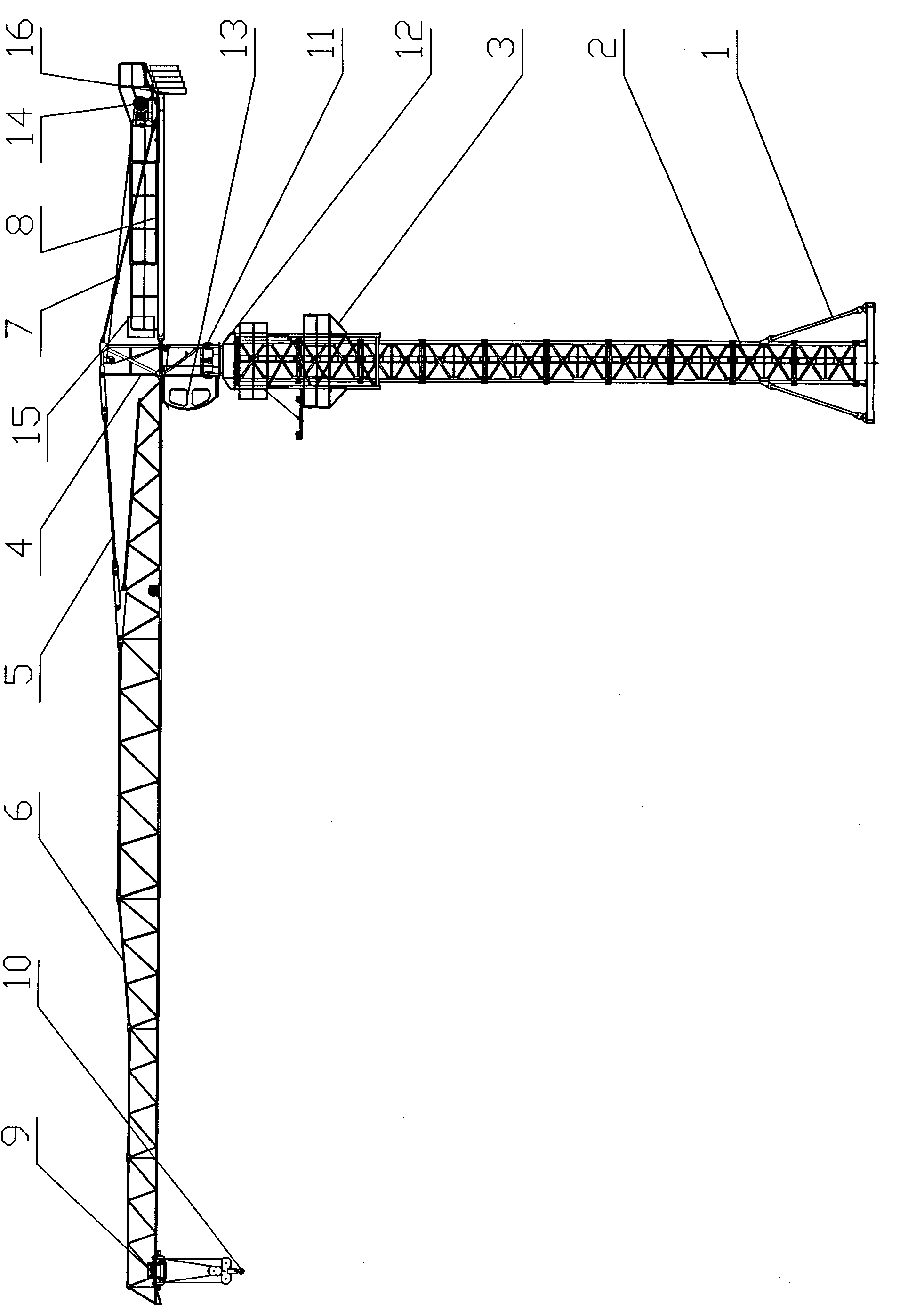
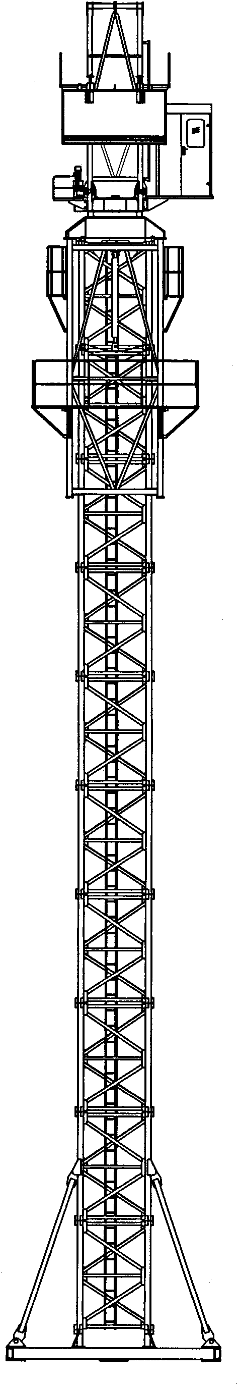
[0020] Flat head tower crane, its composition includes: base frame 1 is used to determine the position of the tower crane and support the whole machine, and a set of standard sections 2 are connected to the base frame in sequence, and the increase and decrease of standard sections can change the structure of the tower crane. The working height of the above-mentioned standard section at the upper end is connected to the slewing assembly, and the slewing assembly is used to complete the slewing operation during the working process of the tower crane, so that the tower crane can complete the rotation of ±540° centering on the tower body. The lower part of the slewing bearing is connected to the sleeve frame 3 located outside the standard section. During the operation, the standard section is separated from the lower support of the slewing bearing. The role of the section. The slewing assembly is connected to the slewing tower body 4 above, and one side of the slewing tower body i...

Embodiment 2

[0022] In the flat-top tower crane, the slewing assembly includes an upper support 11 and a lower support 12, and the upper support is connected to a driver's cab 13.

Embodiment 3

[0024] In the flat-top tower crane, the balance arm has a lifting mechanism 14 and a lifting mechanism electric control box 15, and the rear end of the balance arm has a group of counterweights 16.


PUM


Abstract

The invention provides a flat-head tower crane. The common tower cranes are generally provided with tower tops, and when a group of towers carry out cross operation, the common tower cranes are hard to be competent in many occasions with special requirement for height because of being limited by the tower tops. The flat-head tower crane comprises an undercarriage (1). The invention is characterized in that a group of standard sections (2) are connected on the undercarriage in order; the standard section arranged at the upper end is connected with a swivel assembly; a wrap frame (3) arranged outside the standard sections is connected with the lower part of the swivel assembly and a swivel tower body (4) is connected with the upper part of the swivel assembly; one side of the swivel tower body is connected with a boom (6) by a boom tension bar (5) and the other side thereof is connected with a balance boom (8) by a balance boom tension bar (7); the boom tension bar is connected with a speed changed trolley (9); and a hook (10) is linked with the lower part of the speed changed trolley. The tower crane serves as an elevator.

Description

Technical field: [0001] The invention relates to a flat head tower crane. Background technique: [0002] Ordinary tower cranes generally have a tower top. When hoisting, the lifting equipment needs to have a large lifting height. When installing the boom, it is necessary to connect the boom and tie rods on the ground before hoisting as a whole. At this time Just require hoisting equipment to have very big lifting capacity, and after the arm root pin shaft is connected, the boom will be raised a lot to connect the boom pull rod, and safety accidents are prone to occur at this time. Ordinary tower cranes have tower tops. Generally, when a group of towers crosses, the height difference between each two crossed tower cranes needs to be more than 10m, and it is limited by the tower tops. In many occasions with special requirements for height, such as airports It is difficult for ordinary tower cranes to do the reconstruction and expansion of the tunnel and the construction in th...

Claims


Application Information

Patent Timeline
Patent Type & Authority Applications(China)
IPC IPC(8): B66C23/16B66C23/62
Inventor 芦政军刘宇孟凡波刘俊良朱瑞
Owner HARBIN HUATUO METAL STRUCTURE
Why Eureka
Try Eureka