General reducer with eccentric engagement pairs

A technology of meshing pairs and reducers, which is applied in hoisting devices, transmission devices, components with teeth, etc., can solve the problems of low transmission efficiency, power failure, and motion interference of reducers with small tooth differences, and achieve compact structure , simple and compact, the effect of improving transmission efficiency

Inactive Publication Date: 2010-11-10
CHONGQING UNIV
View PDF4 Cites 18 Cited by
  • Summary
  • Abstract
  • Description
  • Claims
  • Application Information

AI Technical Summary

Problems solved by technology

Due to the cycloidal wheel in the prior art has two kinds of motions, revolution and rotation, part of the motion cannot be used for transmission, resulting in useless high-frequen

Method used


Image

  • General reducer with eccentric engagement pairs
  • General reducer with eccentric engagement pairs
  • General reducer with eccentric engagement pairs

Examples


Embodiment Construction

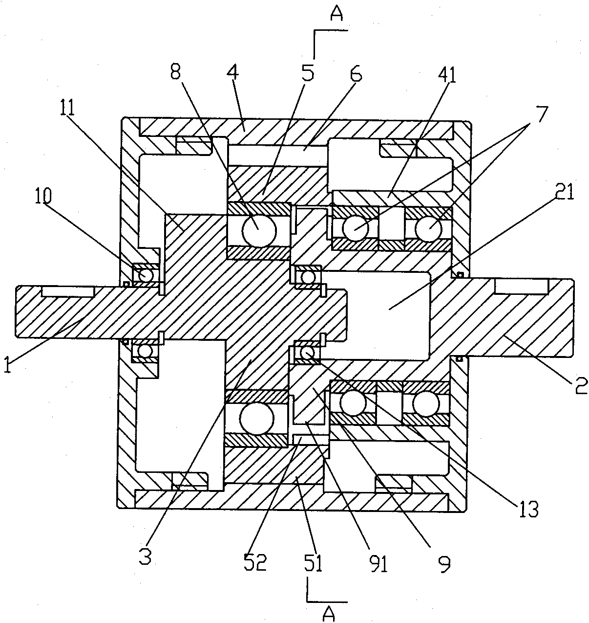
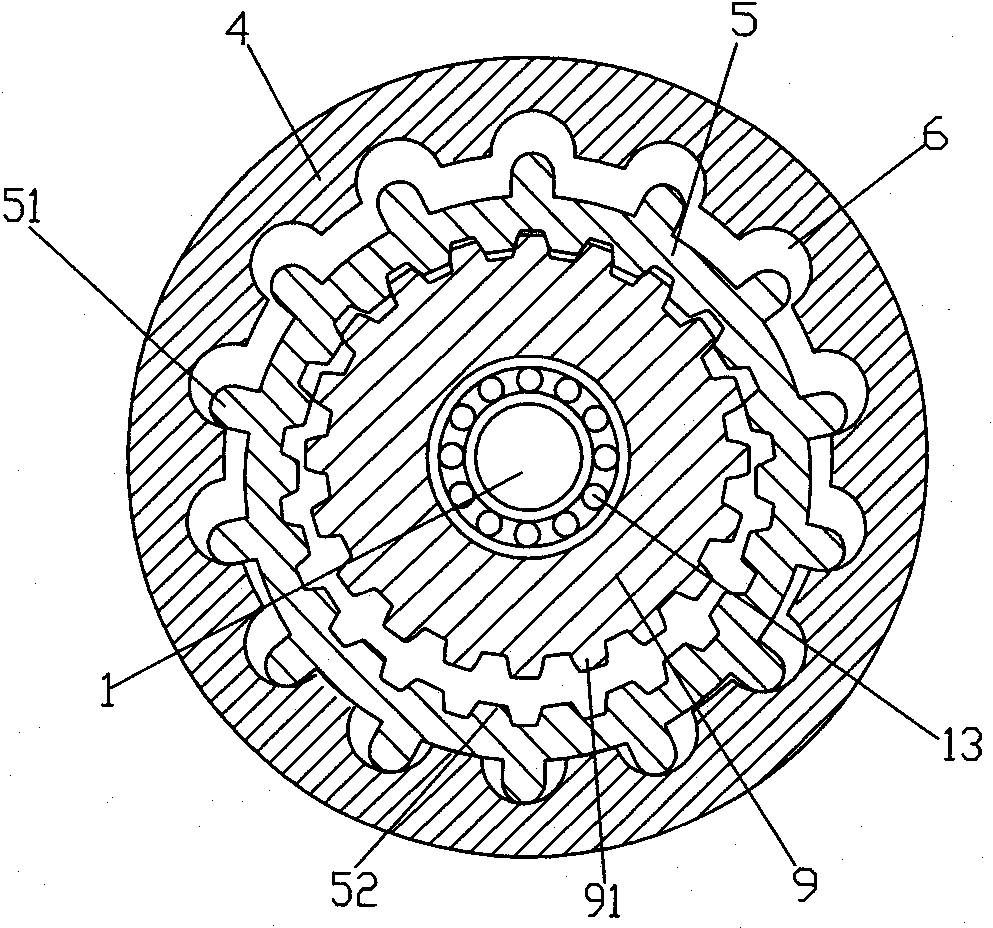
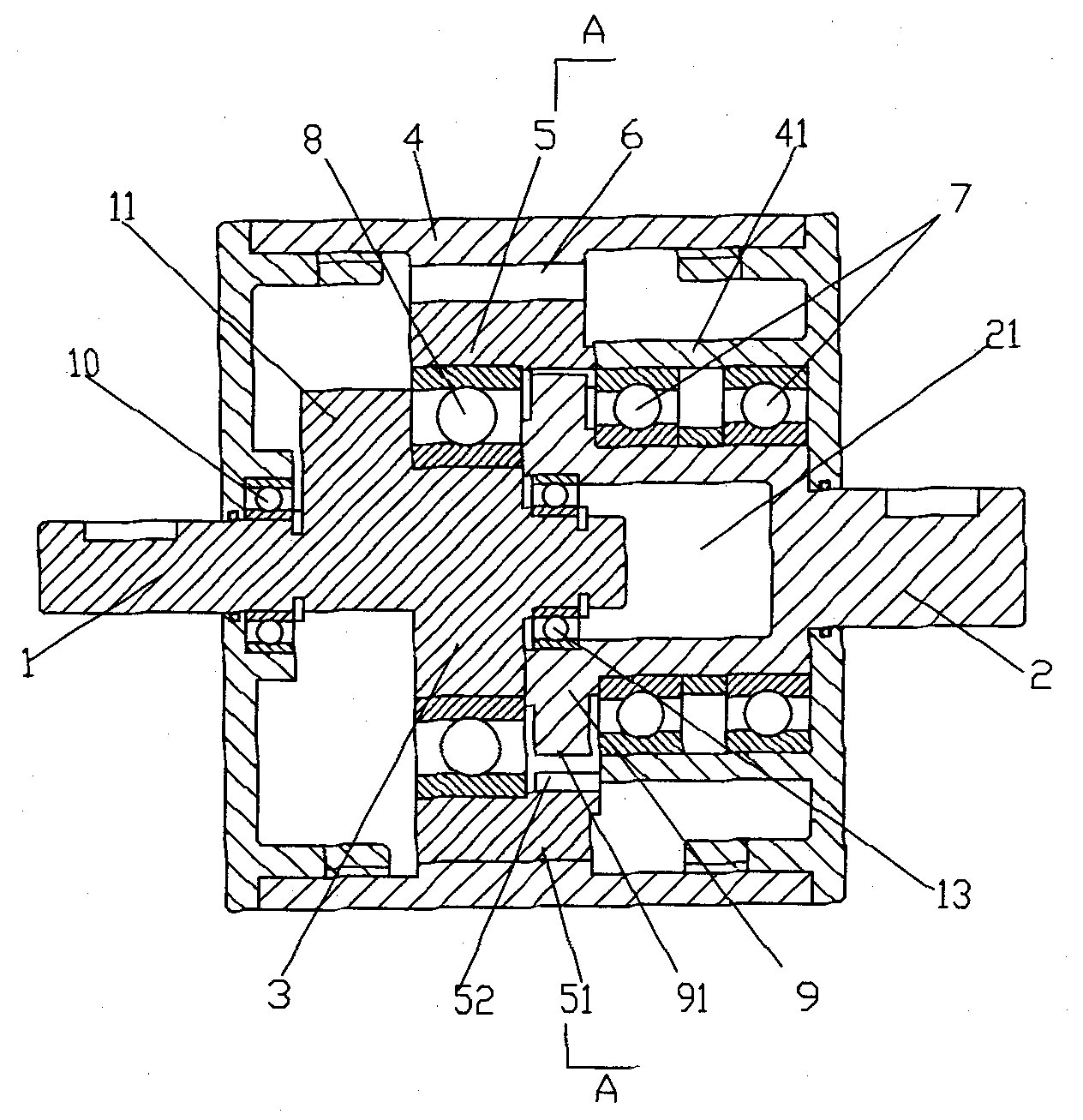
[0017] figure 1 It is a structural schematic diagram of the present invention, figure 2 for figure 1 View along the direction of A-A, as shown in the figure: the universal reducer with eccentric meshing pair in this embodiment includes a housing 4, a power input shaft 1 and a power output shaft 2, and an eccentric sleeve is fixedly arranged on the power input shaft 1 in the circumferential direction 3. The outer circle of the eccentric sleeve 3 is rotated and fitted with a transmission tooth plate 5, and the outer circle of the transmission tooth plate 5 is provided with meshing teeth 51, which are fixed on the housing 4 and are concentric with the power input shaft 1 and are set to mesh with the meshing teeth 51 one by one. Engaging tooth groove 6, the groove width of the engaging tooth groove 6 in the circumferential direction is not narrower than the sum of the tooth width of the engaging tooth 51 in the circumferential direction and twice the eccentricity of the eccentri...


PUM


Abstract

The invention discloses a general reducer with eccentric engagement pairs, comprising a shell, a power input shaft and a power output shaft, wherein an eccentric sleeve is fixedly arranged in the circumferential direction of the power input shaft, is engaged with engaging coggings on the shell by one-to-one correspondence through engaged teeth and is engaged with external gears on the power output shaft in small teeth difference through internal gears. The power input mechanism of the invention adopts the engagement pairs without teeth difference, which is similar to spline engagement, therefore, the relative autorotation speed of the engaging coggings and the engaged teeth is zero and autorotation of a driving fluted disc is eliminated, thus eliminating the high-frequency waves generated in the driving process of the reducers with small teeth different in the prior art, avoiding unnecessary additional motion, improving the driving efficiency and ensuring the motion to be output without hindrance. The general reducer has fewer components than the cycloidal pinwheel reducers in the prior art and has simple and compact structure, small volume and low cost.

Description

technical field [0001] The invention relates to a deceleration device, in particular to a universal decelerator with an eccentric meshing pair. Background technique [0002] The reducer is a device that reduces the high speed of the power machine to the speed suitable for the working machine, and is widely used in the equipment industry. With the development of the equipment industry, higher requirements are put forward for the reducer. The multi-stage gear reducer is widely used in the prior art. The multi-stage gear reducer uses multiple sets of gear meshing pairs to fit the transmission ratio. When the reduction ratio is required to be slightly larger, its structure is complicated and the volume is also large; The gear reducer can obtain a large reduction ratio, but it needs to arrange multiple sets of gears and gear shafts in the radial direction, the structure is relatively complicated, and the structural arrangement is difficult and the volume is large. In order to s...

Claims


Application Information

Patent Timeline
IPC IPC(8): F16H1/28F16H55/02F16H55/17
CPCF16H1/32
Inventor 梁锡昌吕宏展杨仁强
Owner CHONGQING UNIV
Why Eureka
Try Eureka