Flow state display comb tube for automobile wind tunnel

A flow state display, automotive wind tunnel technology, applied in the direction of vehicle testing, measurement devices, instruments, etc., can solve the problems of unable to truly reflect the vehicle or model flow state, large flow field interference, large flow field resistance, etc. Small, reduce interference, easy to operate

Inactive Publication Date: 2010-11-10
JILIN UNIV
View PDF6 Cites 1 Cited by
  • Summary
  • Abstract
  • Description
  • Claims
  • Application Information

AI Technical Summary

Problems solved by technology

There are two disadvantages in the traditional perforated comb tube: 1. The support is a steel beam or a round tube, which is completely in the flow field, which greatly interferes with the flow field, and the smoke flow has been separated before it reaches the test vehicle or model. or vortex; 2. Due to the non-streamline shape of steel beams or round pipes, the flow field resistance is very large. Therefore, the traditional design of smoke flow pipes cannot truly reflect the flow state of cars or models.

Method used


Image

  • Flow state display comb tube for automobile wind tunnel
  • Flow state display comb tube for automobile wind tunnel
  • Flow state display comb tube for automobile wind tunnel

Examples


Embodiment Construction

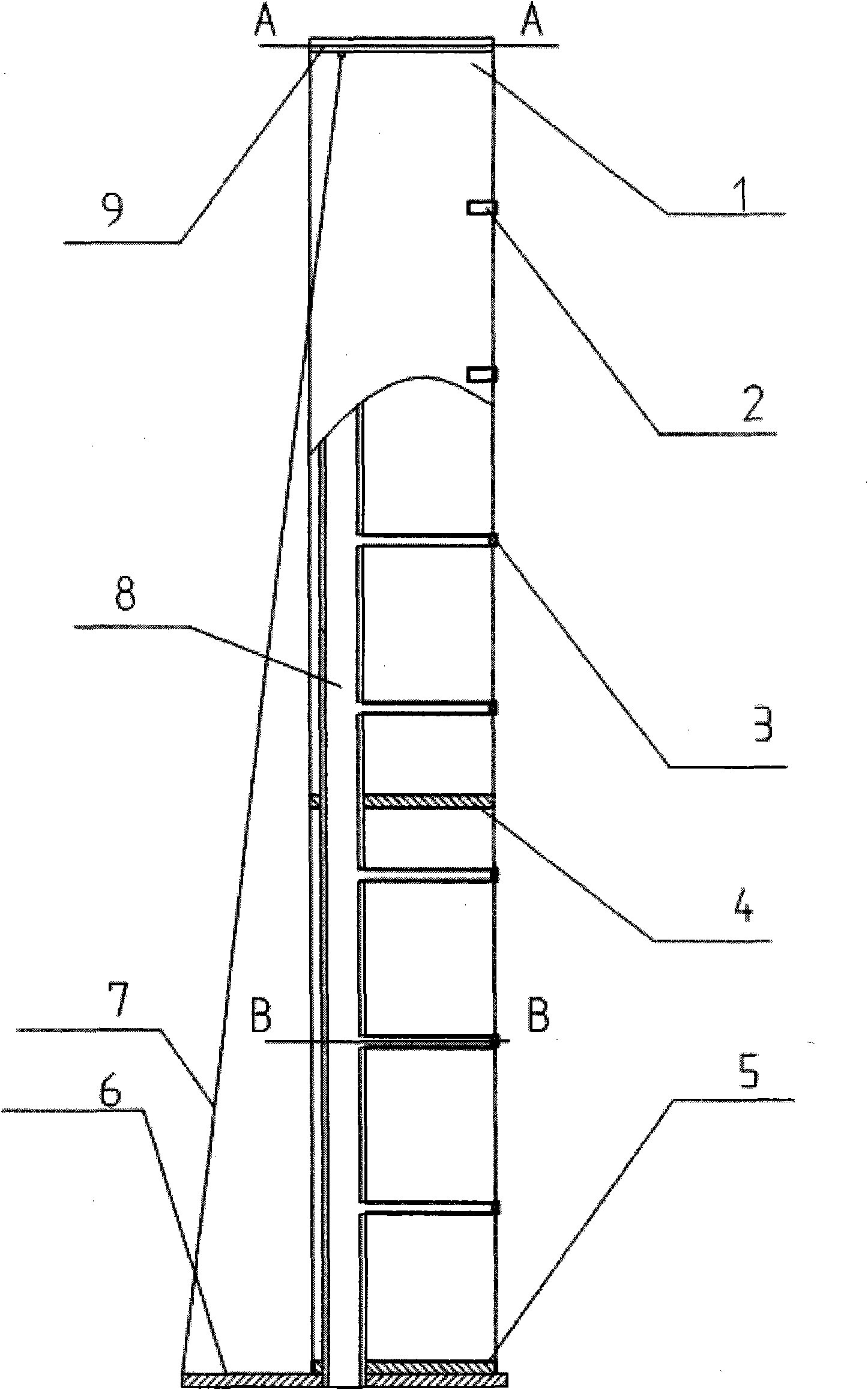
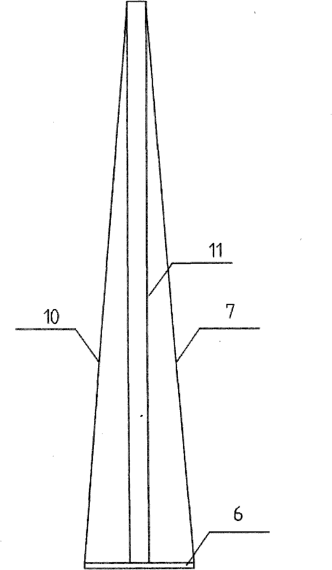
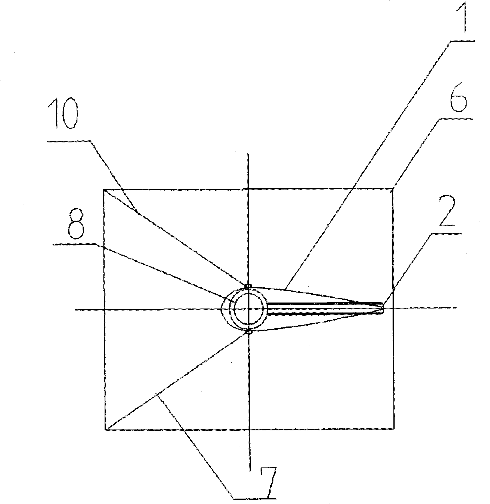
[0022] The present invention is made up of base 6, tension line II 7, tension line I 10 and upper assembly 11, wherein upper assembly 11 is affixed to base 6 through the lower rib 5 thereon; tension line I 10 and tension line The lower ends of the II 7 are respectively affixed to both sides of the base 6, the upper end of the tension line I 10 is affixed to the upper end of one side of the symmetrical airfoil cover 1 of the upper assembly 11, and the upper end of the tension line II 7 is connected to the other side of the symmetrical airfoil cover 1. The upper end of the side is fixedly connected; the base 6 is provided with a through hole.

[0023] The upper assembly 11 is composed of a symmetrical airfoil cover 1, a comb-shaped nozzle 2, a middle rib 4, a lower rib 5, a column tube 8 and an upper rib 9, wherein the side wall of the column tube 8 is provided with equidistant through holes, Each through hole is fixedly connected to and communicated with one end of each comb-sh...


PUM


Abstract

The invention discloses a flow state display comb tube for an automobile wind tunnel belonging to the technical field of automobile wind tunnel tests, which is composed of a base, a tension line II, a tension line I and an upper assembly, wherein the upper assembly is fixedly connected with the base through a lower reinforcing rib thereon; the lower ends of the tension line I and the tension line II are respectively fixedly connected to two sides of the base; the upper end of the tension line I is fixedly connected with the upper end at one side of a symmetrical wing-type ladle lid of the upper assembly; the upper end of the tension line II is fixedly connected with the upper end at the other side of the symmetrical wing-type ladle lid of the upper assembly; and the base is provided with a through hole. The drag coefficient of the invention is nearly zero; the comb tube has little obstruction on flow, can effectively reduce interference thereof on the flow field of the automobile wind tunnel, prevent separation and reduce influence on flow field quality of a test section; and the operation is convenient, and multi-point smoke flow state visualization can be realized from a model to the whole automobile aiming at automobiles with different proportions.

Description

technical field [0001] The invention belongs to the technical field of automobile wind tunnel experiments, and in particular relates to a comb tube for displaying the flow state of an automobile wind tunnel. Background technique [0002] When carrying out the display experiment of the whole vehicle or the model smoke flow state in the general automobile wind tunnel, the beam support fixed between the top wall and the bottom wall is used, and the round tube with holes is fixed on it, and the holes are arranged according to a certain distance. Arrangement, or directly fix a round tube with holes with a certain rigidity and strength between the top wall and the bottom of the wind tunnel, and the holes on the tube are arranged at a certain distance, so that the smoke flowing through the tube is blown by the wind tunnel airflow through the holes The negative pressure sucks out, thereby forming a comb-shaped smoke flow, and the smoke flow state of a certain section of the car is f...

Claims


Application Information

Patent Timeline
Patent Type & Authority Applications(China)
IPC IPC(8): G01M9/04G01M17/007
Inventor 胡兴军王靖宇范爱华杨博范士杰王新宇张英朝叶辉乔银波董春波
Owner JILIN UNIV
Why Eureka
Try Eureka