
Liquid crystal display device

A liquid crystal display device, liquid crystal panel technology, applied in nonlinear optics, instruments, optics, etc., can solve problems such as weak grounding, quality failure, adhesion failure, etc., and achieve the effect of preventing loosening failure, improving quality, and preventing electrostatic failure.

Inactive Publication Date: 2010-11-10
LG DISPLAY CO LTD
View PDF0 Cites 17 Cited by
  • Summary
  • Abstract
  • Description
  • Claims
  • Application Information

AI Technical Summary

Problems solved by technology

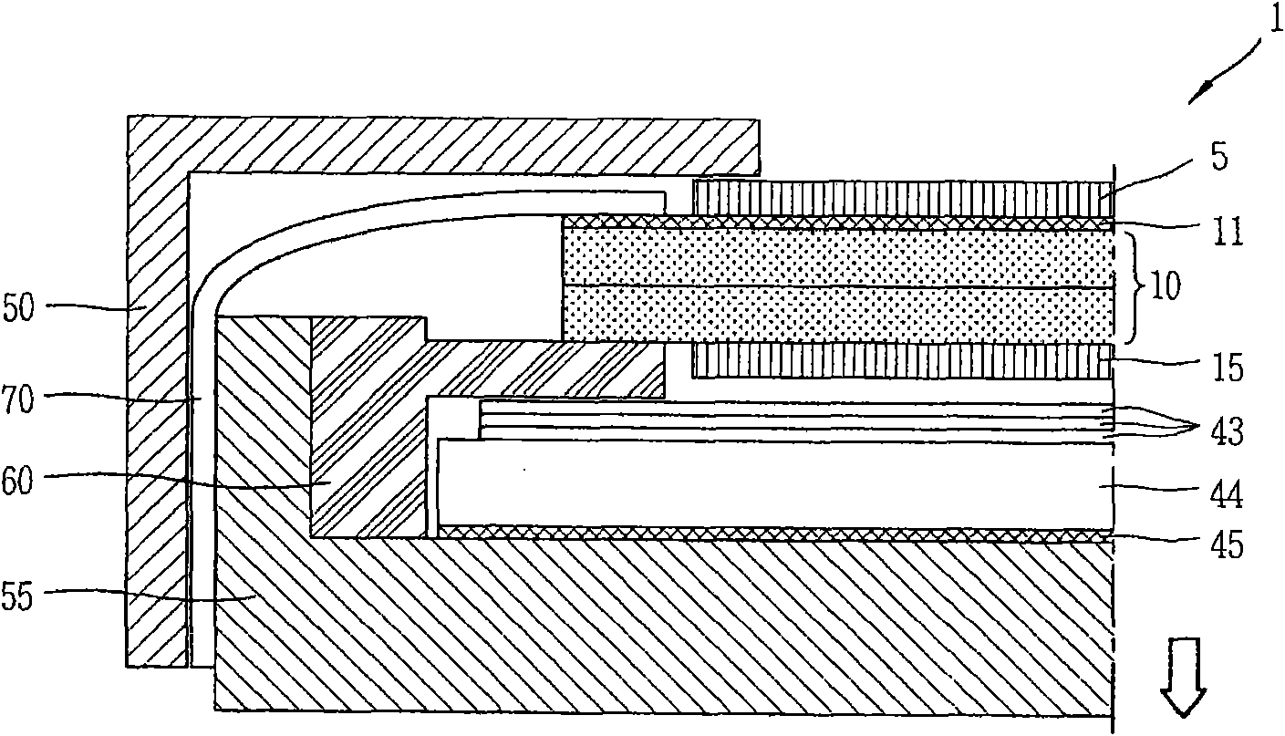
[0020] In addition, in the case of using the supporting body 60 cast structure, the upper ITO 11 is grounded to the bottom case 55 using the grounding strap 70, and at this time because the attachment area of ​​the grounding strap 70 is small, it may cause quality failure due to weak grounding
Also, there may be a possibility of attachment failure when attaching the ground strap 70 due to such a small ground panel
[0021] At this time, as shown in the figure, in the case of increasing the thickness of the bottom case 55 in the direction of the arrow to ensure the attachment area of ​​the ground strap 70, the problem that the overall thickness of the liquid crystal display device 1 is also increased
Specifically, in a small-sized module below 5 inches, the increase in the thickness of the liquid crystal display device 1 may not be able to meet the user's requirement for a thin liquid crystal display device.
[0022] On the other hand, in the case of fastening the liquid crystal panel to the backlight assembly using a guide plate, the upper ITO is grounded toward the guide plate as a pressing part, and there may be a possibility that the grounding belt is separated after the attachment part of the upper ITO attached to the color filter substrate. failure problem

Method used


Image

  • Liquid crystal display device
  • Liquid crystal display device
  • Liquid crystal display device

Examples


Embodiment Construction

[0036] A liquid crystal display device according to a preferred embodiment of the present invention will be described in detail below with reference to the accompanying drawings.

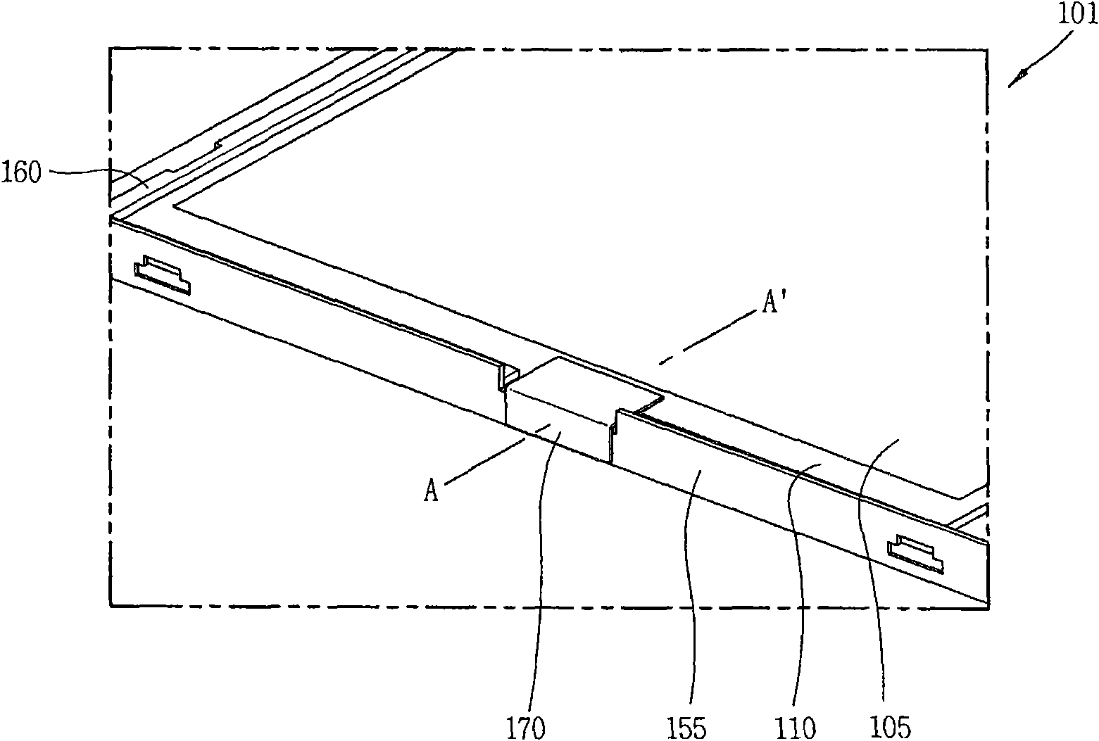
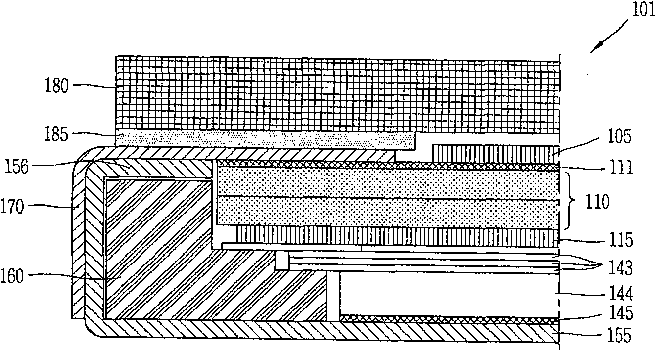
[0037] figure 2 is a cross-sectional view schematically illustrating a liquid crystal display device according to an embodiment of the present invention, and image 3 is schematically illustrated along the figure 2 A view showing a cross-section cut by the A-A' line in the liquid crystal display device according to the embodiment of the present invention.

[0038] As shown in the figure, the panel area 101 of a liquid crystal display device according to an embodiment of the present invention may include: a liquid crystal panel 110 for displaying images; and housing components, such as the supporting body 160 and the bottom case 155, which are used to accommodate and fix the liquid crystal panel 110 and the backlight assembly.

[0039] At this time, although not specifically shown in the drawing...


PUM


Abstract

A liquid crystal display device strengthens an adhesive force of an electrostatic prevention means without increasing a thickness of the liquid crystal display device by bending part of the bottom cover thereof into a C -shape, thereby securing a space for adhering an upper indium tin oxide (ITO) of the color filter substrate and the electrostatic prevention means, in a small-sized model having an in-plane switching (IPS) mode liquid crystal panel, and the liquid crystal display device may include a liquid crystal panel configured with a color filter substrate and an array substrate to display an image; a backlight assembly arranged at a rear surface of the liquid crystal panel to supply light to the liquid crystal panel; a support main for accommodating and fixing the liquid crystal panel and the backlight assembly; a bottom cover fastened to the support main to include at least one bending portion in which part thereof is bent in a C -shape; and a electrostatic prevention means adhered to cover part of an upper ITO of the liquid crystal panel including the bending portion of the bottom cover.

Description

technical field [0001] The present invention relates to a liquid crystal display device, and more particularly, to an upper ITO layer for enhancing an antistatic device and a color filter substrate in a small-sized module of a liquid crystal panel having an in-plane switching (IPS: in-plane switching) mode Attachment between liquid crystal display (LCD) devices to prevent ground faults. Background technique [0002] In the recent information society, the importance of display devices is more emphasized as a visual information transmission medium, but they should meet requirements such as low power consumption, thin appearance, light weight, and high image quality to occupy an important position in the future. [0003] Display devices are mainly classified into emissive displays capable of emitting light spontaneously, such as cathode ray tube (CRT), electroluminescence (EL), light emitting diode (LED), vacuum fluorescent display (VFD: vacuum fluorescent display), field emiss...

Claims


Application Information

Patent Timeline
Patent Type & Authority Applications(China)
IPC IPC(8): G02F1/1362G02F1/13
CPCG02F1/13338G02F2202/22G02F1/13452G02F1/1333
Inventor 具衡谟
Owner LG DISPLAY CO LTD
Learn More