Cooperative data transmission method and system

A technology for collaborative transmission and data, applied in the field of communication

Inactive Publication Date: 2010-11-10
ZTE CORP
View PDF2 Cites 19 Cited by
  • Summary
  • Abstract
  • Description
  • Claims
  • Application Information

AI Technical Summary

Problems solved by technology

[0009] In view of this, the main purpose of the present invention is to provide a method and system for coordinated multi-point transmission to solve how to meet the downlink data allocation requirements of the joint processing method in the prior art

Method used


Image

  • Cooperative data transmission method and system
  • Cooperative data transmission method and system
  • Cooperative data transmission method and system

Examples


example 1

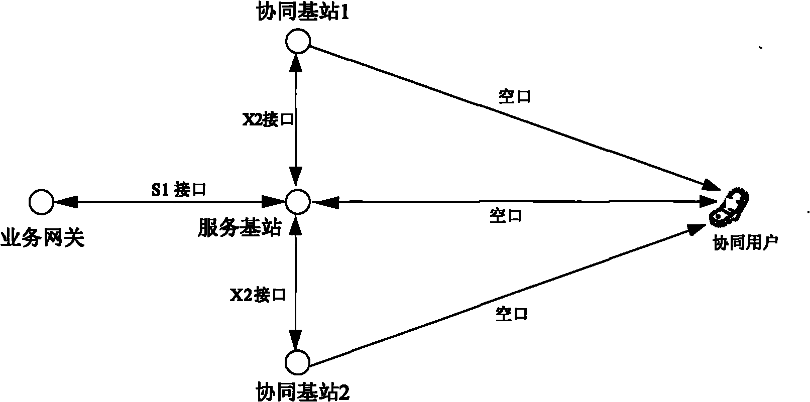
[0059] figure 1 As shown in the figure, it is a schematic diagram of the data distribution of scheme 1. The method of scheme 1 is that the service gateway treats the cooperative user data and the non-cooperative user data in the same way, and does not perform special processing; the service gateway transmits the user data through S1 The interface is delivered to the serving base station of the user, so that the serving base station receives the coordinated user data and non-cooperative user data within its service range; for the non-cooperative user data, the serving base station performs air interface processing and transmits it to the non-cooperative user through the transmitting antenna.

[0060] For cooperative user data, the serving base station first transmits the user data to other cooperative base stations in the cooperative group through the X2 interface according to the cooperative group information of the user. The candidate coordinating base station sends a coordin...

example 2

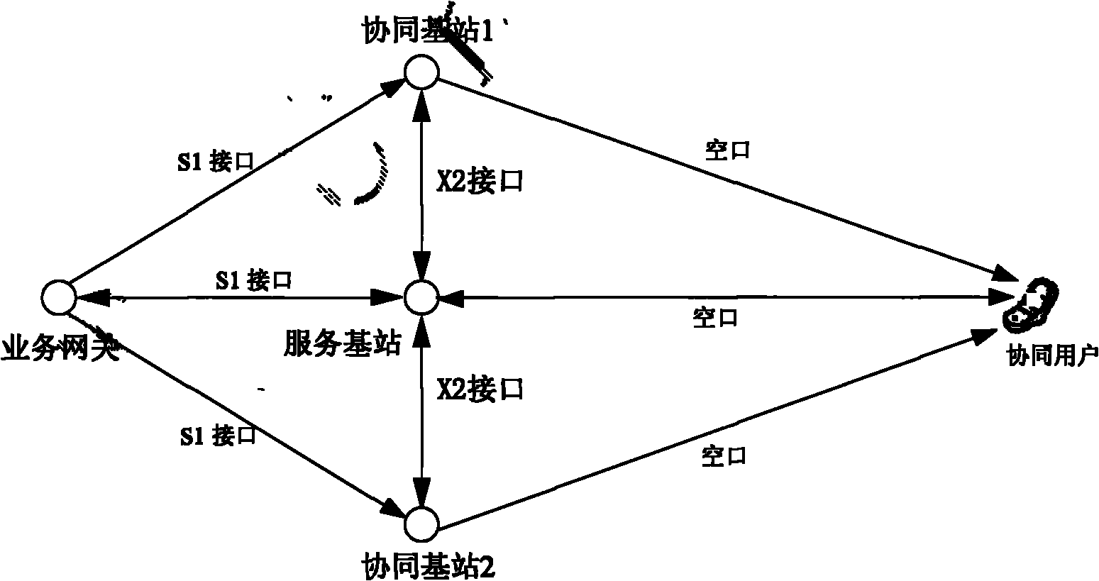
[0070] figure 2 As shown in the figure, it is a schematic diagram of data delivery in scheme 2. The method of scheme 2 is that, for non-cooperative user data, the service gateway sends the data to the user's serving base station through the S1 interface. For the coordinated user data, the serving base station judges the coordinated user, and the method of forming a coordinated group is the same as that in Embodiment 1. The service gateway sends it to all members in the coordinated group through the S1 interface, including the serving base station and each coordinated base station. All the base stations directly receive the coordinated user data from the service gateway, so that there is no need to transmit the downlink data of the coordinated user between the serving base station and the coordinated base station, and the control plane only needs to exchange cooperative control signaling. After the cooperative control signaling interaction is completed, the serving base statio...

example 3

[0080] Scheme 2 is also adopted, and the schematic diagram of data delivery is as follows figure 2 , wherein the functions of the service gateway, the serving base station, the coordinated base station and the coordinated user are the same as those in Example 1.

[0081] Flowchart such as Figure 5 As shown, the service gateway transmits the user data to the serving base station of the user through the S1 interface according to the method specified in the current LTE. For the sake of clarity, it is set that the user data received by the serving base station includes the data of user a and the data of user b.

[0082] Based on the channel quality information fed back by users a and b, the serving base station determines that the serving base station itself cannot provide high-quality transmission for user a due to time-varying channels, and needs to perform coordinated transmission for user a, so that user a becomes a cooperative user; user b is still only provided by the ser...


PUM


Abstract

The invention discloses a cooperative data transmission method and a cooperative data transmission system. In the scheme of the invention, a service base station judges whether a user needing cooperative transmission exists or not according to channel quality information fed back by the user, if so, the service base station builds a cooperative group, a service gateway transmits downlink service data to cooperative group members through an S1 interface according to information uploaded by the service base station and the cooperative group members transmit obtained downlink service data to the cooperative user through an X2 interface. The method and the system have the advantages of solving the problem of downlink service data in cooperative transmission, allowing the service base station and each cooperative base station to obtain the downlink service data of the cooperative user, performing cooperative transmission on the cooperative user, meeting the requirement on downlink data distribution in a joint processing mode, adding additional processing for an access network side or improving gateway capability without causing any effect on the service distribution of non-cooperative users.

Description

technical field [0001] The present invention relates to the communication field, in particular to a method and system for cooperatively transmitting data. Background technique [0002] With the introduction of LTE-A (Long-Term Evolution Advanced, referred to as LTE-A) requirements, people pay more and more attention to the average spectral efficiency of the cell and the spectral efficiency of the cell edge. In comparison, the spectral efficiency of the cell edge is the most important People are concerned that this is mainly because the uplink and downlink of the LTE-A system is a frequency division system with OFDM (Orthogonal Frequency Division Multiplexing, OFDM for short) (or some variation of OFDM) as the basic multiple access method, and Unlike traditional wireless communication systems that use CDMA (Code-Division Multiple Access, referred to as CDMA) as the basic multiple access multiplexing method, the LTE-A system has no processing gain, and the inside of the cell i...

Claims


Application Information

Patent Timeline
Patent Type & Authority Applications(China)
IPC IPC(8): H04W28/18H04B7/02H04B7/04
CPCH04B17/0042H04B17/0067H04B17/309H04B17/24
Inventor 张晨晨朱常青姜静孙云锋
Owner ZTE CORP
Why Eureka
Try Eureka