Agitation grinder

A grinder and agitator technology, applied in the field of agitator grinders

Active Publication Date: 2010-11-17
BUEHLER AG
View PDF7 Cites 9 Cited by
  • Summary
  • Abstract
  • Description
  • Claims
  • Application Information

AI Technical Summary

Problems solved by technology

In such agitator grinders, the concentrating of the grinding medium in the region of the container wall is achieved by means of the vane-shaped structure of the agitator; grinding media) and reliable separation of grinding media without risk of operational failure

Method used


Image

  • Agitation grinder
  • Agitation grinder
  • Agitation grinder

Examples


Embodiment Construction

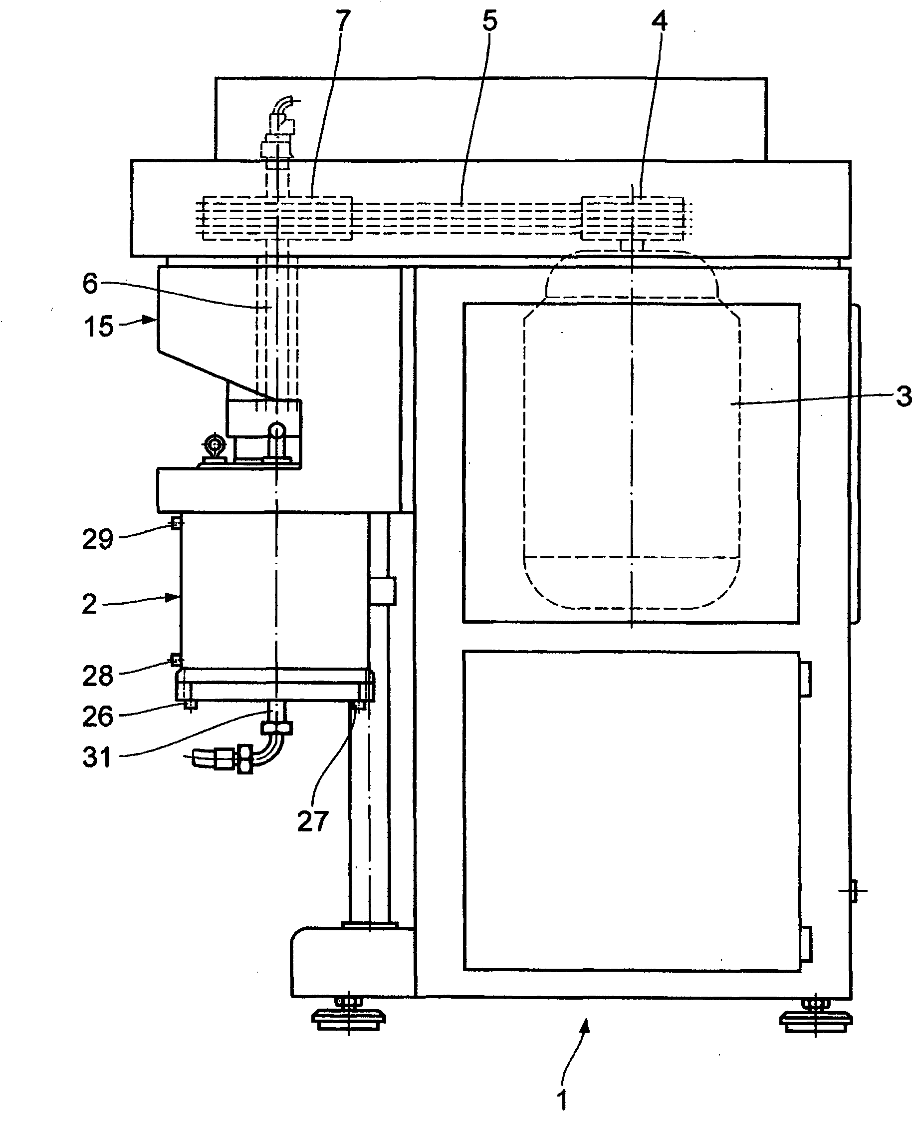
[0026] figure 1 The agitator mill shown in generally has a column 1 on which a cylindrical grinding container 2 can be mounted. In the column 1 is mounted a drive motor 3, which is equipped with a V-belt 4, through which a V-belt 7 is rotatably driven by means of a V-belt 5, which is connected to the drive The shaft 6 is connected in a rotationally fixed manner.

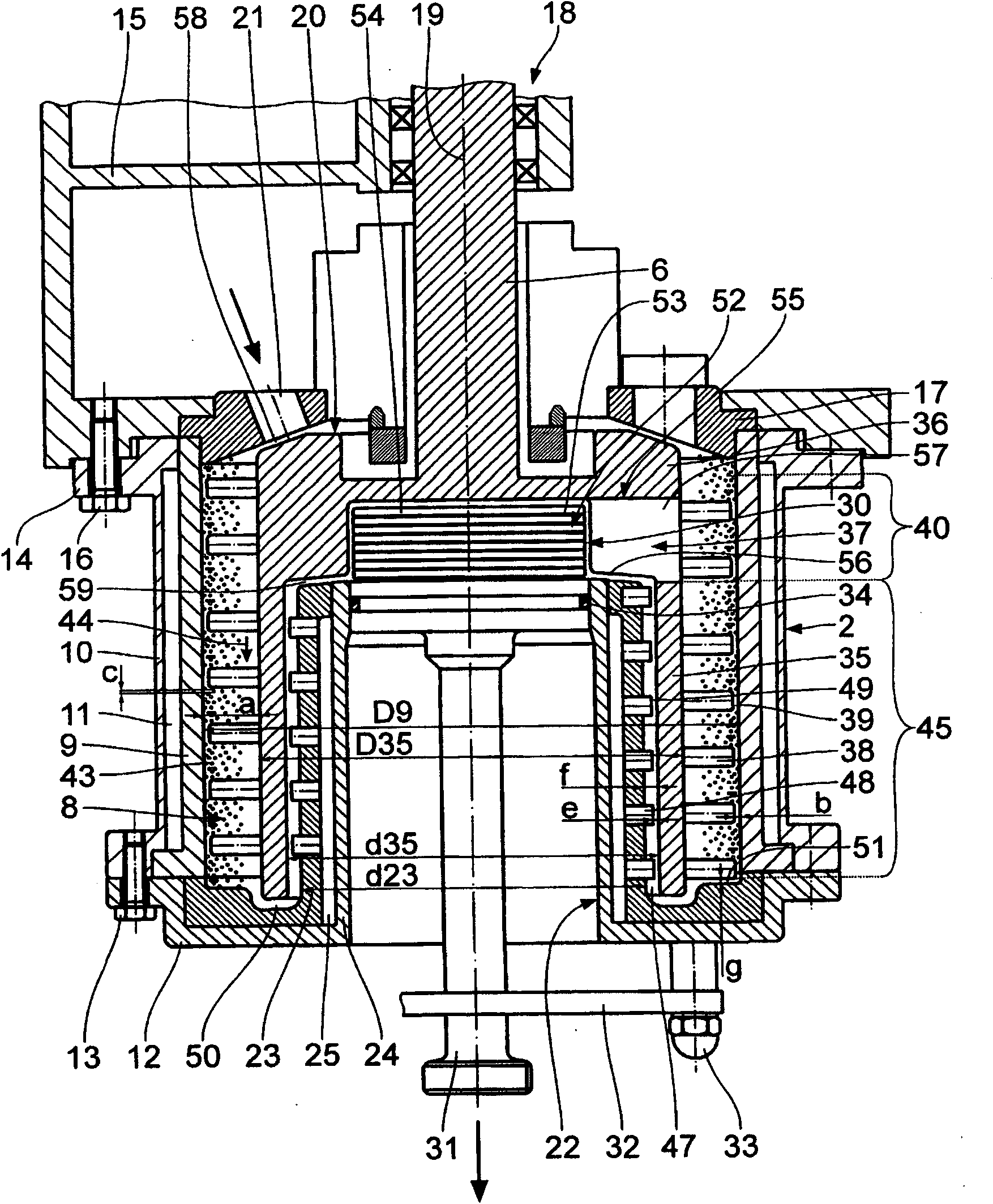
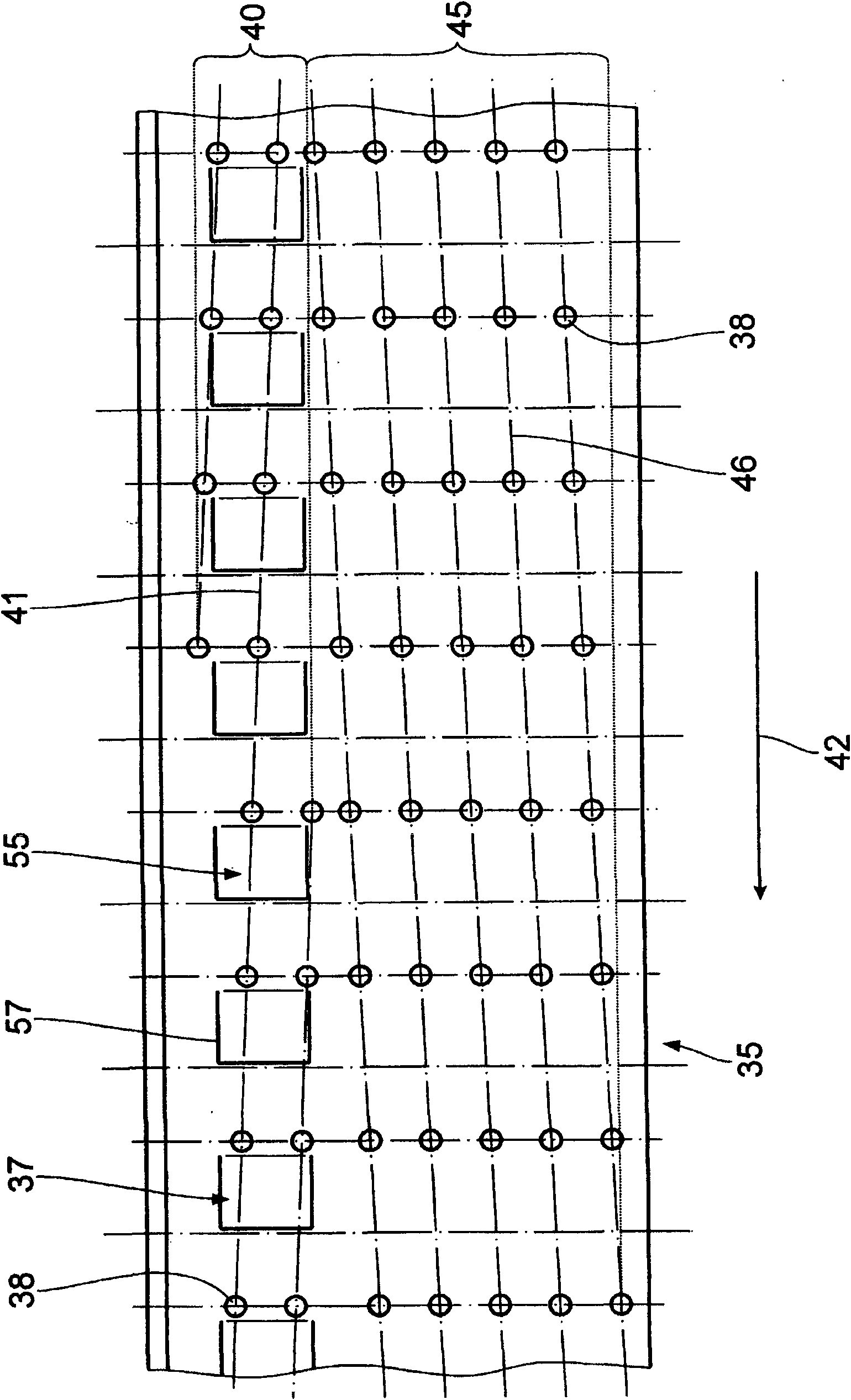
[0027] as in particular by figure 2 and 3 It can be seen that the grinding container 2 has a cylindrical container wall 9 surrounding the grinding chamber 8 , which is surrounded by an essentially cylindrical cooling housing 10 . A cooling chamber 11 is formed between the container wall 9 and the cooling housing 10 . The lower end of the grinding chamber 8 is formed by an annular bottom plate 12, which is fixed on the grinding container 2 with screws 13.

[0028] The grinding container 2 has an upper annular flange 14, by means of which it is fastened with screws 16 to the bottom of a support housing 15 mounted...


PUM


Abstract

The invention relates to an agitation grinder used for processing the grinding material with fluid ability. The grinder comprises a grinding container (2) and an inner stator (22) arranged in the grinding container, wherein a ring cylindrical rotor (35) which can be driven to rotate is arranged between the inner stator (22) and the wall (9) of the container, the rotor and the wall (9) of the container encircle to form a grinding cavity (8); a grinding material output channel (47) is formed between the rotor (35) and the inner stator (22), the grinding material output channel is connected with the grinding cavity (8) with the help of a steering channel (50); and the grinder is provided with a device used for preventing grinding medium (43) from entering the grinding material output channel (47) through the grinding cavity (8).

Description

[0001] This application is a divisional application of the patent application 200580051811.3 with the filing date of October 11, 2005 and the title of "Stirring Grinder". technical field [0002] The invention relates to an agitated mill according to the preamble of claim 1 . Background technique [0003] An agitator mill of this type is known from EP 0 370 022 B1 (corresponding to US 5,062,577). In such agitated mills, the grinding medium is centrifugally separated from the grinding stock-grinding medium flow through the grinding medium recirculation channel before reaching the protective screen. Here, the protective screen basically serves the function of collecting worn grinding medium that is too light to be thrown off directly through the grinding medium recirculation channel and serves as a throttle element for building up a back pressure against the grinding flow. The stirrer is equipped with stirring tools that protrude into the external grinding chamber. When usin...

Claims


Application Information

Patent Timeline
Patent Type & Authority Applications(China)
IPC IPC(8): B02C17/16
Inventor N·施特尔P·施米特
Owner BUEHLER AG
Why Eureka
Try Eureka