

Low profile wrench
A wrench and head technology, applied in the field of hand tools, to achieve the effect of increasing operability and reducing production time
- Summary
- Abstract
- Description
- Claims
- Application Information
AI Technical Summary
Problems solved by technology
Method used
Image

Examples
Embodiment Construction
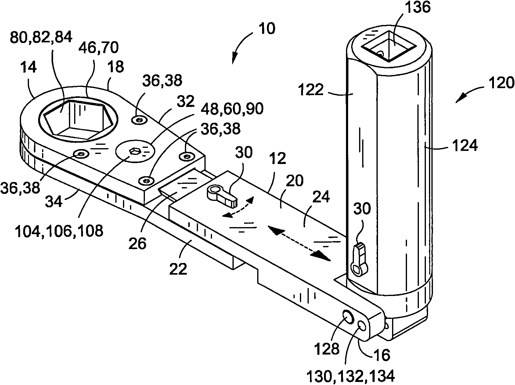
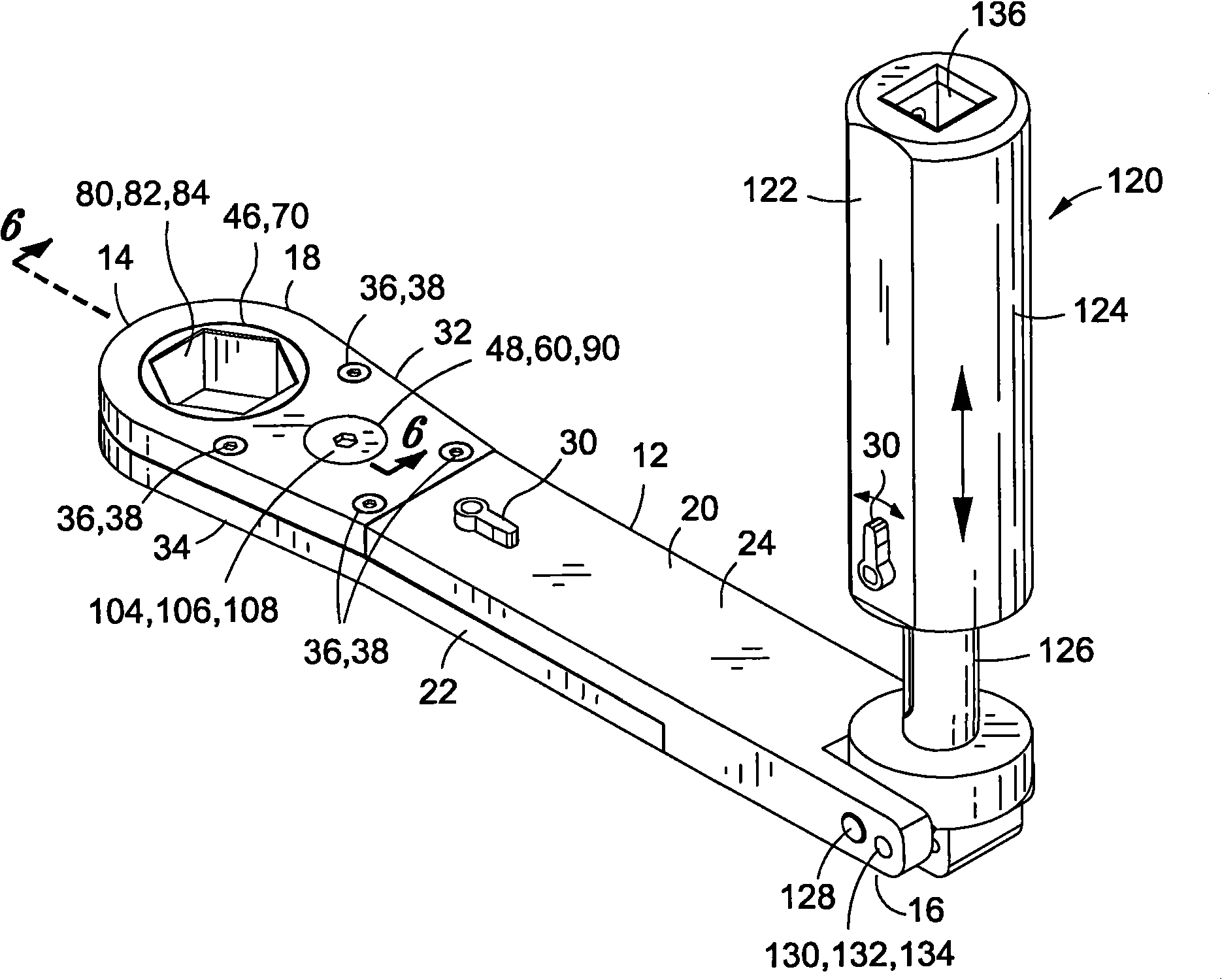
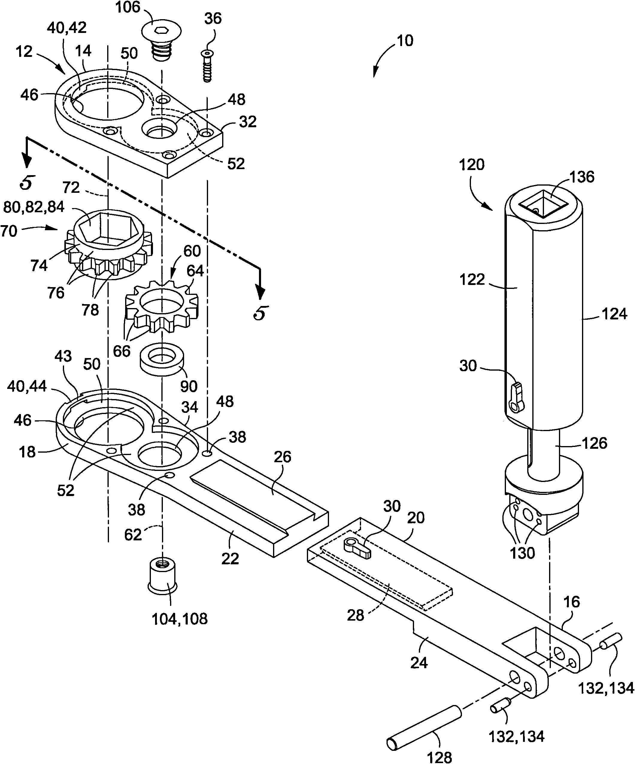
[0026] Referring now to the drawings, which are for the purpose of illustrating preferred and various embodiments of the invention only and not for the purpose of limiting the same, in Figure 1 to Figure 3Shown in is a low profile wrench 10 for installation with a fastener 160 of reduced upper operability and / or reduced rotational operability. Broadly speaking, the wrench 10 includes an elongated body 12 and a drive mechanism 80 incorporated into the body 12 . The drive mechanism 80 may be supported on an irreversible, one-way directional roller clutch 90 . Advantageously, the one-way directional roller clutch 90 provides a ratchet mechanism with minimal or substantially zero backlash.
[0027] specific reference figure 1 as well as figure 2 , in an embodiment, the body 12 of the wrench 10 may have a plurality of opposed ends including a tool end 14 and a handle end 16 and including a head portion 18 and a handle portion 20 . The drive mechanism 80 may be generally house...
PUM
 Abstract
Description
Claims
Application Information