Ratchet wrench

A ratchet wrench and gear technology, applied in the field of wrenches, can solve the problems of difficult control, the ratchet wrench is not very obvious, etc., and achieve the effects of simple structure, easy control and use, and easy assembly and processing.

Inactive Publication Date: 2010-11-17
孙 成纲
View PDF8 Cites 2 Cited by
  • Summary
  • Abstract
  • Description
  • Claims
  • Application Information

AI Technical Summary

Problems solved by technology

Such as the "ratchet wrench" disclosed in Chinese patent CN2389754Y, the ratchet wrench is provided with an accommodating hole in the head of the wrench, in which a ratchet wheel is provided, and the wrench is provided with an accommodating groove for accommodating teeth, and the end of the accommodating groove is provided with a The bead hole has a spring and a steel ball inside, and the steel ball is against the top of the tooth. Although the ratchet wrench has a simple structure and can realize the unidirectional rotation of the tooth, the ratchet wrench controls the ratchet wrench through the structure of the steel ball and the tooth. , can only control the ratchet wrench to idle left or right, that is to say, the ratchet wrench has only two control functions, and there is no intermediate gear, that is to say, the ratchet wrench can only idle to the right or to the left, and cannot be fixed Does not idle in middle gear
And such a ratchet wrench is not very obvious and difficult to control when shifting gears

Method used


Image

  • Ratchet wrench
  • Ratchet wrench
  • Ratchet wrench

Examples


Embodiment Construction

[0020] The present invention will be further described in detail below in conjunction with the accompanying drawings and embodiments.

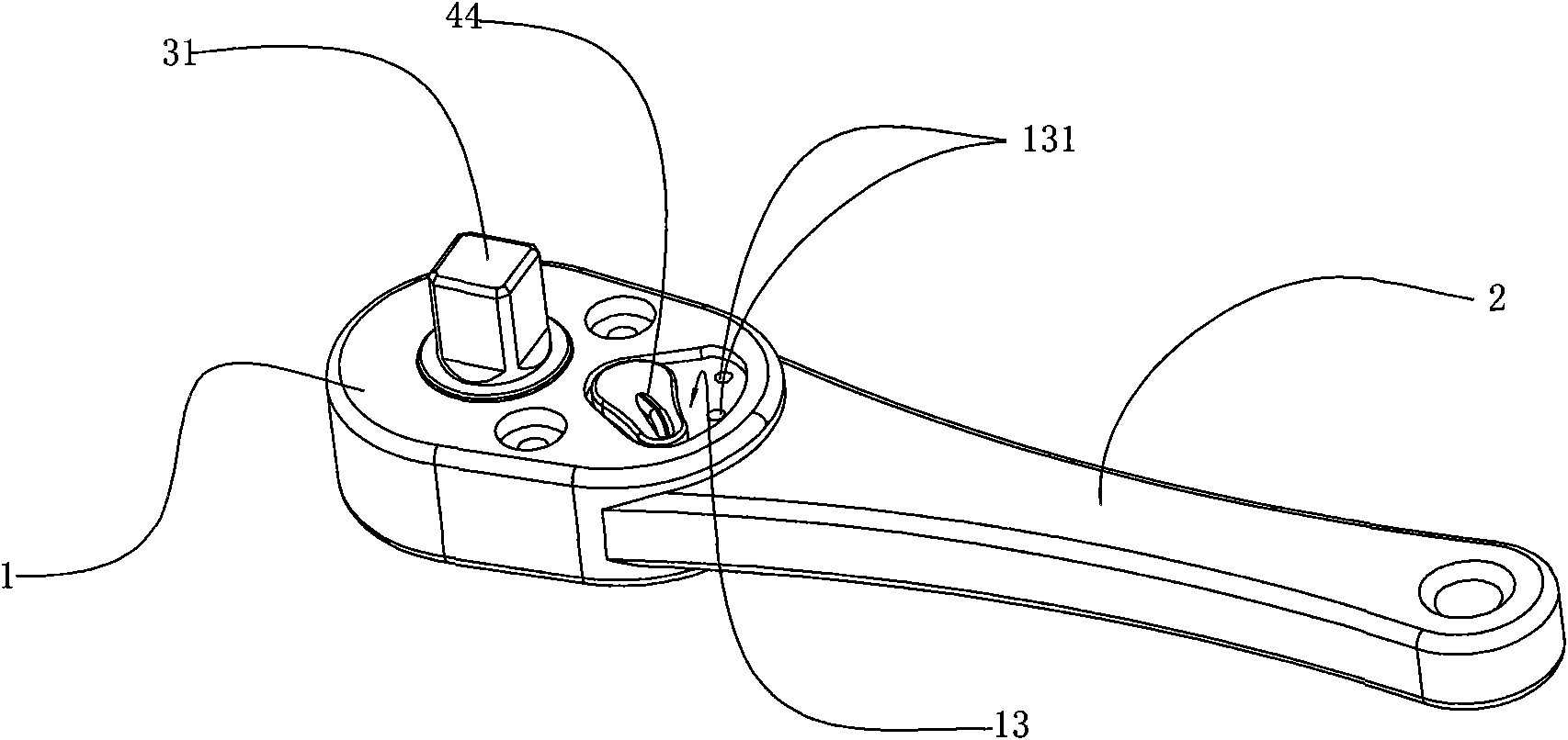
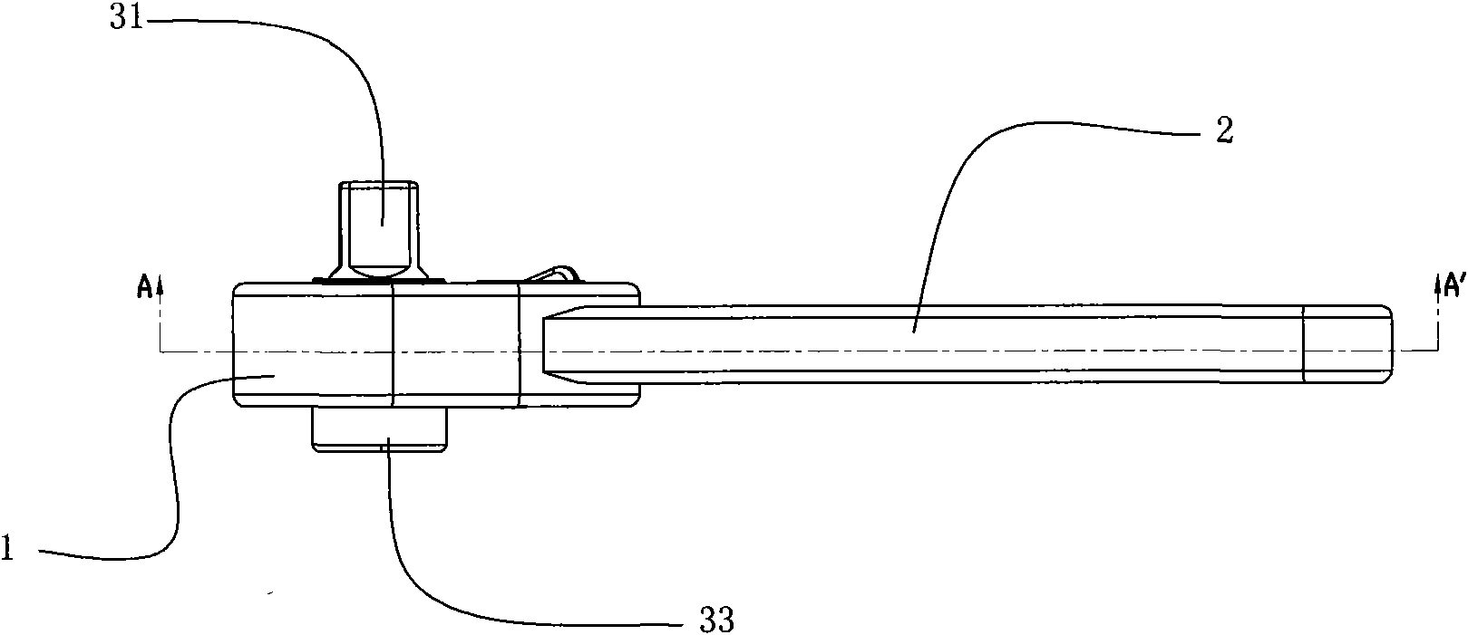
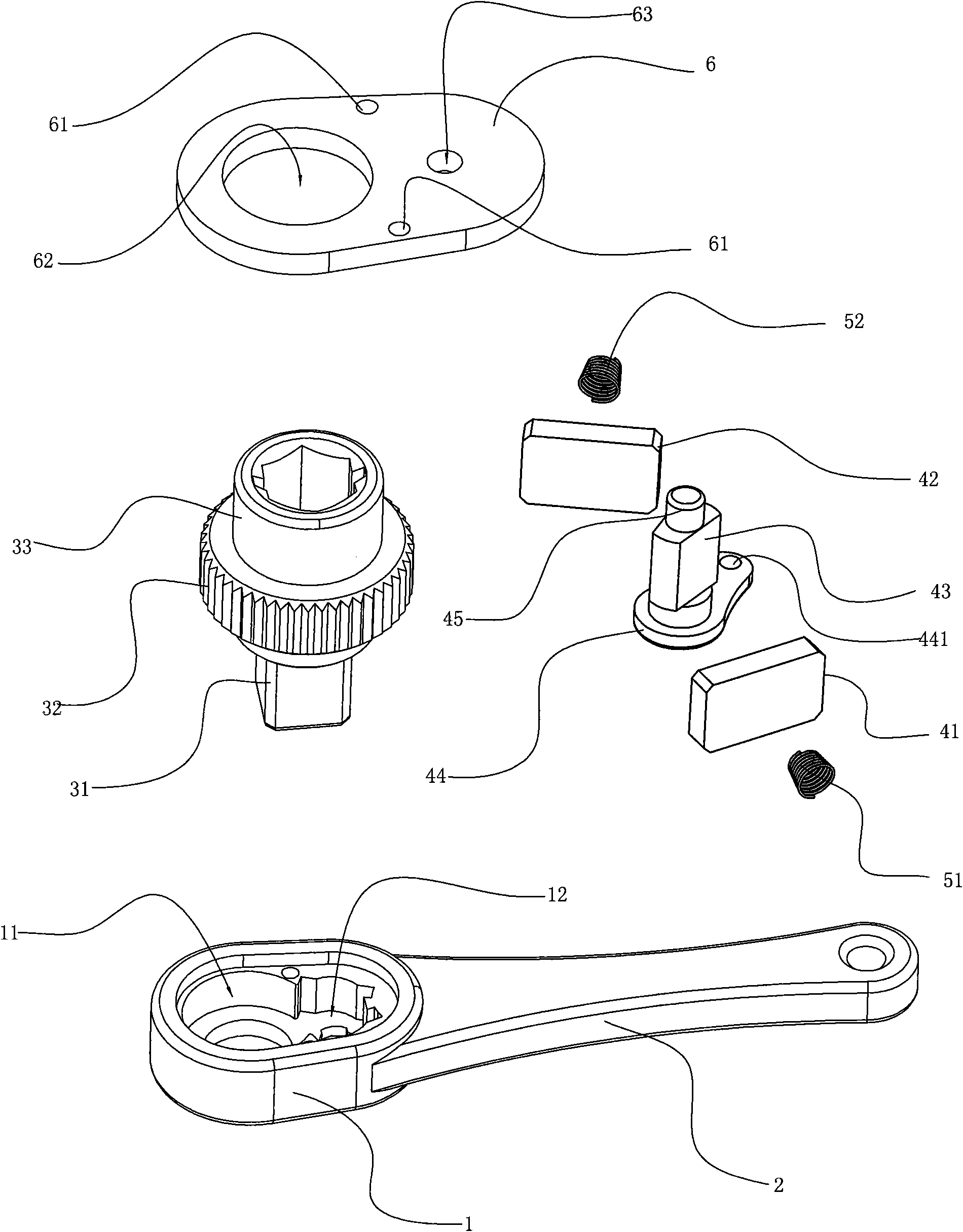
[0021] Ratchet wrench of the present invention, as Figure 1-5 As shown, it includes the head 1 of the wrench and the handle part 2 connected with the head 1. The head 1 has a through hole 11 for accommodating the gear assembly, and the bottom 31 of the gear assembly protrudes from the through hole 11. The gear part 32 of the gear assembly is placed in the step of the through hole 11, and the top of the gear part 32 has a connecting head 33 protruding from the head 1 of the wrench. The connecting head 33 can have holes of various shapes for Connect external nuts or bolts. The bottom 31 of the gear assembly protruding from the head 1 can also be a cube. The shape of the bottom 31 can be designed to connect sockets of different sizes to become a socket wrench. The sockets of different sizes can be suitable for connecting external objects of dif...


PUM


Abstract

The invention discloses a ratchet wrench, which comprises a head, a handle, and a gear component and a brake component positioned in the head. The gear component comprises a gear element, a connecting head positioned on the upper part of the gear element, and a bottom positioned on the lower part of the gear element; the gear element is positioned in a through hole of the head; the connecting head and the bottom respectively extend out of the head and positioned outside the head; and the brake component is positioned in a groove near the through hole of the head and close to the handle. Through the arrangement of the gear component and the brake component of the ratchet wrench, a control block can control left and right control pieces to realize unidirectional locking and bidirectional rotary locking of the ratchet wrench and further realize the clockwise and anticlockwise idling of the wrench so as to facilitate loosening or tightening nuts or bolts.

Description

technical field [0001] The invention relates to a wrench, in particular to a ratchet wrench. Background technique [0002] Wrench is a tool commonly used in production activities, it has a variety of functions, including adjustable wrench, socket wrench and so on. However, in some narrow spaces, it is sometimes inconvenient to use these wrenches, because it takes many turns to tighten a bolt or nut, and ordinary wrenches cannot turn 360 degrees, and the wrench needs to be removed from the bolt or nut, and then Choose a suitable angle to repeat the action. Such pulling is not only complicated and inefficient, but also may cause the rotation of the bolt or nut, making it very inconvenient to tighten the bolt or nut. [0003] Therefore, some ratchet wrenches have appeared, which can control the wrench to only move in one direction without causing rotation. Such as the "ratchet wrench" disclosed in Chinese patent CN2389754Y, the ratchet wrench is provided with an accommodating...

Claims


Application Information

Patent Timeline
Patent Type & Authority Applications(China)
IPC IPC(8): B25B13/46B25B23/00
Inventor 沈佰勇孙成纲
Owner 孙 成纲
Why Eureka
Try Eureka