Safety cutter

A cutting knife, safety technology, applied in the direction of metal processing, etc., can solve the problems of damage, personal injury items, cutting edge safety, etc., and achieve the effect of convenient use

Inactive Publication Date: 2010-11-17
MERIDIAN INT
View PDF6 Cites 9 Cited by
  • Summary
  • Abstract
  • Description
  • Claims
  • Application Information

AI Technical Summary

Problems solved by technology

[0003] Existing cutting knives are basically divided into three types: the first type is that the blade is fixed relative to the knife body, and the cutting edge of the blade is exposed outside the knife body and cannot be retracted. Although it is convenient to use, it is always exposed. There are potential safety hazards in the cutting edge, and careless operation and negligence may easily cause personal injury or damage to objects; the second is that the blade can be extended and retracted relative to the knife body under the action of the user's push and pull, which is safe. Compared with the first type of cutting knife whose blade is always exposed, it is better, but it increases the user's action and labor intensity; the third type is that the blade can be stretched out under the push of the user, and once the user releases the pushing mechanism, the blade will It can be automatically retracted to the inside of the knife body under the force of a spring or the like. The disadvantage of this design is that the user must consciously release the pushing mechanism, otherwise the blade will always be exposed outside the knife body

Method used


Image

  • Safety cutter
  • Safety cutter
  • Safety cutter

Examples


Embodiment Construction

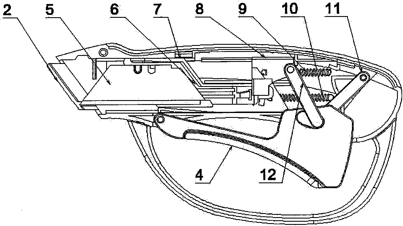
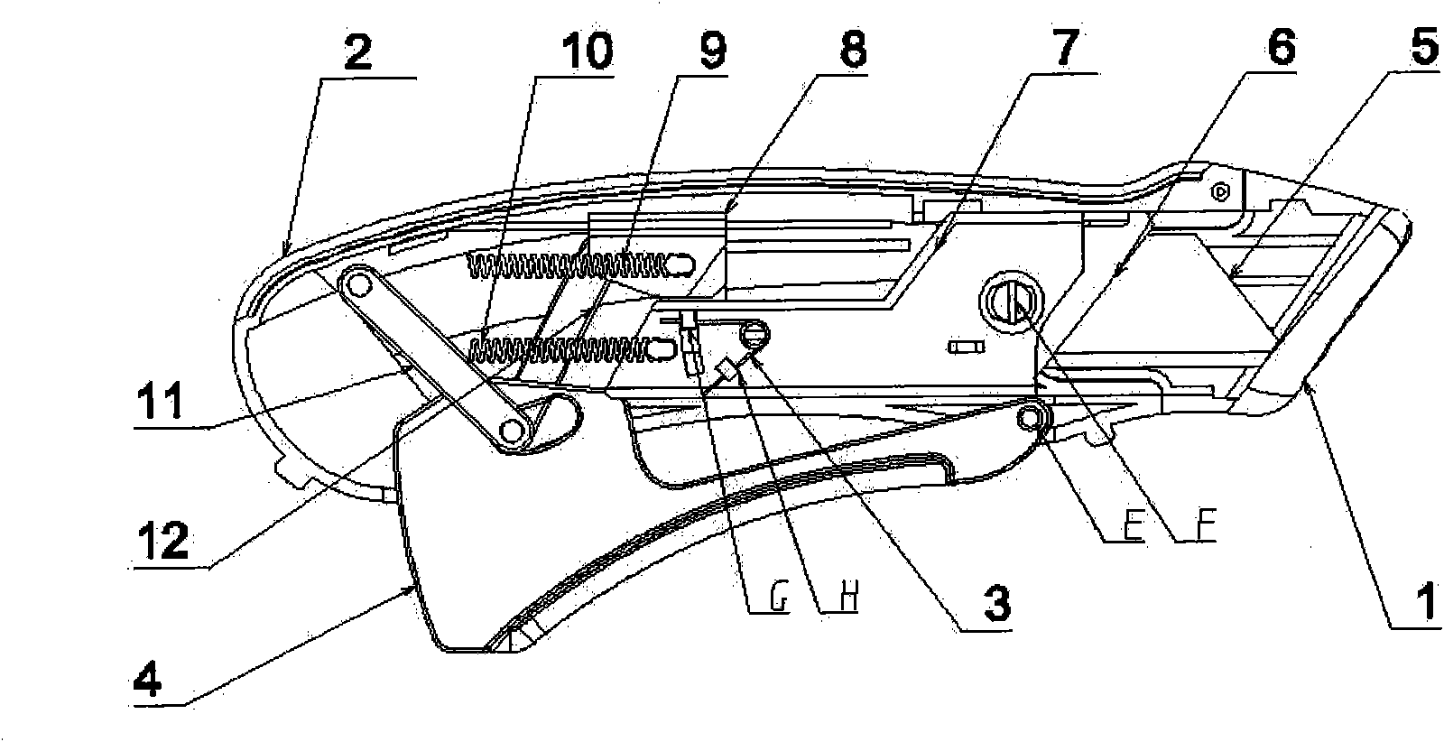
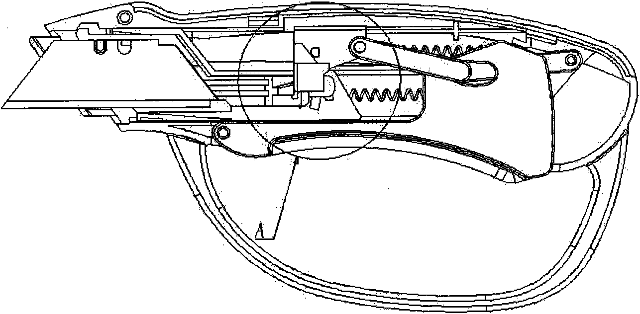
[0016] The casing 2 of the present invention is a snap-fit ​​connection structure of left and right halves. In the figure, the surface layer casing is removed to clarify the internal structure of the present invention.

[0017] figure 1 with figure 2 It is a schematic diagram of the internal structure of the present invention. It can be seen from the figure that a safety cutting knife includes a housing 2, a detachable blade protective cover 1 placed at the end of the housing 2, and a fixed connection with the rotating knife rest 6. The blade 5 is characterized in that: the two ends of the tension spring one 9 in the cavity of the housing 2 are respectively connected to the housing 2 and the slider 8, and the two ends of the tension spring two 10 are respectively connected to the housing 2 and the sliding tool holder 7; one end of the trigger 4 Connected to the housing 2 through the fulcrum E, the other end of the trigger 4 can move up and down around the fulcrum E; It is c...


PUM


Abstract

The invention belongs to the technical filed of tools, which relates to a safety cutter and is characterized in that two ends of a tension spring 1 in a cutter shell cavity are respectively connected with a shell and a slide fastener; two ends of a tension spring 2 are respectively connected with the shell and a slide rest; one end of a trigger is connected with the shell through a supporting point E; one end of a connection rod 2 is connected with the slide fastener, and the other end is connected with one end of a connection rod 1 through a round hole above the trigger; the other end of the connection rod 1 is connected with the shell; the slide rest is connected with a cylindrical embossment F on a rotary tool rest in a button placement mode and can rotate for an alpha angle around the cylindrical embossment F; two ends of a torsional spring are respectively connected with a salient point G of the rotary tool rest and a salient point H of the slide rest; and the slide fastener is connected with the slide rest in a slide mode, and can be jointed or separated with the abutting side of the rotary rest. The invention has the beneficial effect that a blade can automatically stretch out under the driving of the squeezed trigger, realize the cutting function, and is convenient to use; and when the cutting operation ends, the blade can automatically retract into the shell at once even the trigger is not loosened, thereby having no potential safety hazard.

Description

technical field [0001] The invention belongs to the technical field of knives, and in particular relates to a safety cutting knife whose blade can retract automatically. Background technique [0002] The cutting knife is a basic cutting tool, which has the advantages of sharp edge, durable, replaceable blade, strong cutting force and fast cutting speed, so it is widely used in the fields of life, construction and manufacturing. [0003] Existing cutting knives are basically divided into three types: the first type is that the blade is fixed relative to the knife body, and the cutting edge of the blade is exposed outside the knife body and cannot be retracted. Although it is convenient to use, it is always exposed. There are potential safety hazards in the cutting edge, and careless operation and negligence may easily cause personal injury or damage to objects; the second is that the blade can be extended and retracted relative to the knife body under the action of the user's...

Claims


Application Information

Patent Timeline
Patent Type & Authority Applications(China)
IPC IPC(8): B26B1/08B26B1/10
Inventor 张玉军
Owner MERIDIAN INT
Why Eureka
Try Eureka