Thermal management system of electric automobile

A thermal management system and technology for electric vehicles, applied in the field of thermal management systems for electric vehicles, can solve the problems of high technical difficulty in manufacturing charge and discharge protection circuits, increased labor intensity for installation workers, and difficulty in solving safety problems thoroughly, thereby improving electrochemical performance. The effect of response speed, elimination of safety hazards, and simple structure

Active Publication Date: 2013-01-30
李辉 +1
View PDF0 Cites 0 Cited by
  • Summary
  • Abstract
  • Description
  • Claims
  • Application Information

AI Technical Summary

Problems solved by technology

The larger the capacity of the batteries connected in series, the more difficult it is to make the charge and discharge protection circuit, and it is difficult to completely solve its safety.
The series and parallel connection of a large number of flexible packages also increases the labor intensity of the installation workers, and there are great safety hazards in loading, unloading, transportation and assembly
In addition, the motor and motor controller have a temperature rise during work, and the motor and motor controller have a higher temperature rise during the high-speed driving of an electric vehicle. Excessive temperature may cause damage to the motor and controller, making it difficult to use The service life is short, which wastes resources; and because the operating environment temperature of electric vehicles is generally -20 ~ +55 ℃, the space in the cabin is small, and the temperature is too high or too low to make people feel uncomfortable

Method used


Image

  • Thermal management system of electric automobile
  • Thermal management system of electric automobile
  • Thermal management system of electric automobile

Examples


Embodiment Construction

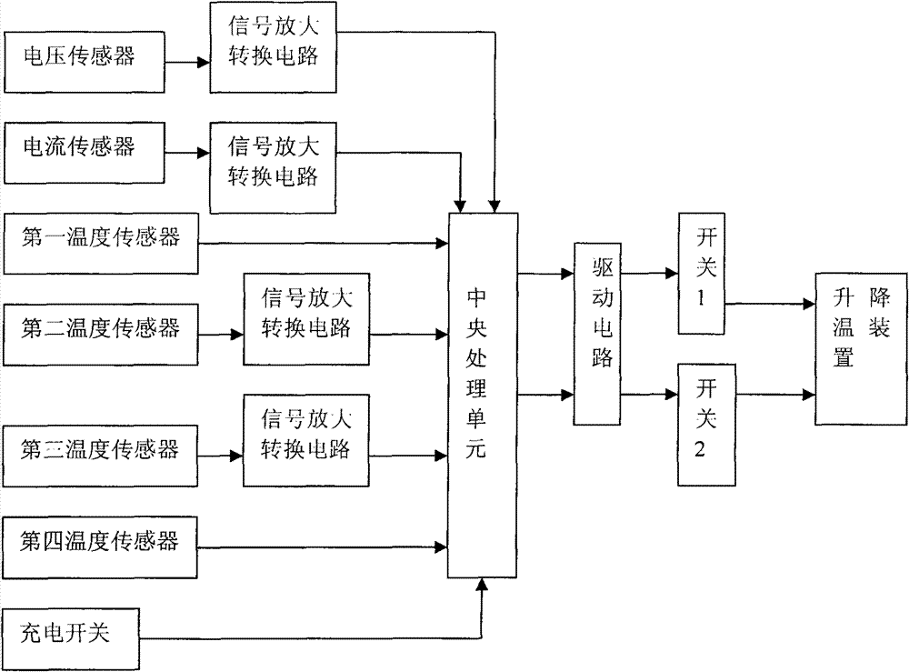
[0026] Such as figure 1 As shown, the electric vehicle thermal management system of the present invention includes a first temperature sensor, a second temperature sensor, a third temperature sensor and a fourth temperature sensor, a central processing unit, and a heating and cooling device, and the first temperature sensor is used to be placed in the battery pack , the second temperature sensor is used to be set inside the motor; the third temperature sensor is used to be set at the motor controller, and the fourth temperature sensor is used to be set in the electric vehicle compartment, and the electric compartment is also provided with a refrigerator and a heater ; The first temperature sensor and the fourth temperature sensor adopt DS18B20, the second temperature sensor and the third temperature sensor adopt PT100, the signal output ends of the second temperature sensor and the third temperature sensor are respectively connected with the input ends of the signal amplificati...


PUM


Abstract

The invention discloses a thermal management system of an electric automobile, comprising a temperature sensor, a heating and cooling device and a central processing unit, wherein the temperature sensor is used for acquiring the temperature of components generating the raising and the drop of temperature in the electric automobile; the heating and cooling device is used for generating a heat source and a cold source which are transmitted to components needing heating and cooling and is connected with the signal output end of the central processing unit through a control switch; and the central processing unit is used for receiving a signal of the temperature sensor and calculating and outputting the control signal to the heating and cooling device. In the invention, the temperature conditions of various components can be detected by using the temperature sensor and are transmitted to the central processing unit which controls the temperature in time so as to ensure that the temperatures of various components are in a proper range. The system not only can be used for monitoring the temperature of batteries, but also can be used for monitoring the temperature of a motor and a motor controller, thereby avoiding the motor and the motor controller from being damaged due to overhigh temperature. The system can also be used for monitoring the temperature in a carriage and ensures thecomfort degree of the moving space of people.

Description

technical field [0001] The invention relates to an electric vehicle, in particular to a heat management system for the electric vehicle. Background technique [0002] At present, lithium batteries are generally used in electric vehicles. The ambient temperature of lithium batteries in electric vehicles is generally -20 to +55°C, and the extreme low temperature in low temperature environments may be as low as below -40°C. As far as a single cell is concerned, the capacity retention rate at 0°C is about 60-70%, the capacity retention rate at -10°C is about 40-55%, and the capacity retention rate at -20°C is about 20-50%. 40%. Under such low temperature conditions, the electrochemical reaction speed decreases, the output current and voltage of the battery will decrease, and the discharge capacity will also decrease significantly. Such low temperature performance obviously cannot meet the requirements of power sources. On the contrary, in a high temperature environment, the li...

Claims


Application Information

Patent Timeline
Patent Type & Authority Patents(China)
IPC IPC(8): H01M10/50B60R16/02B60K1/04B60H1/00H01M10/42H01M10/617H01M10/625
CPCY02E60/12Y02E60/10
Inventor 李久学李辉李立
Owner 李辉
Why Eureka
Try Eureka