
Semi-automatic electrically controlled clutch system

A clutch and semi-automatic technology, applied in the direction of magnetic drive clutch, non-mechanical drive clutch, clutch, etc., can solve the problems of high price, development impact, high maintenance cost and fuel consumption, and achieve easy maintenance, simplified gear operation and reduced fuel consumption and production cost effects

Inactive Publication Date: 2010-11-17
ZHEJIANG UNIV
View PDF4 Cites 3 Cited by
  • Summary
  • Abstract
  • Description
  • Claims
  • Application Information

AI Technical Summary

Problems solved by technology

However, it requires precise adjustment of complex gear systems, so its high price is prohibitive, and its high maintenance cost and fuel consumption also have a certain impact on its development

Method used


Image

  • Semi-automatic electrically controlled clutch system
  • Semi-automatic electrically controlled clutch system
  • Semi-automatic electrically controlled clutch system

Examples


Embodiment Construction

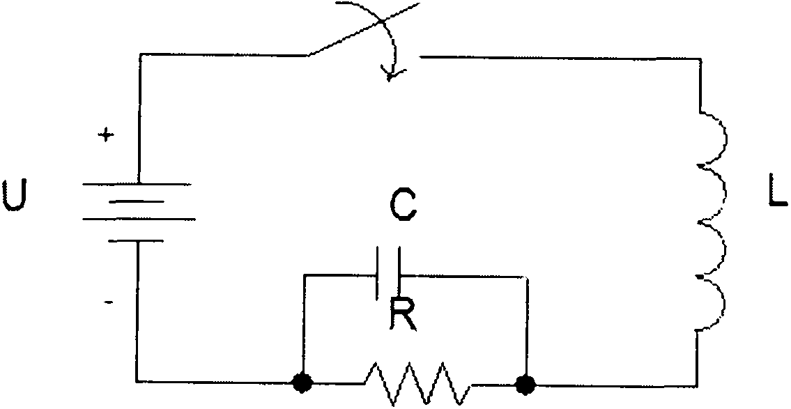
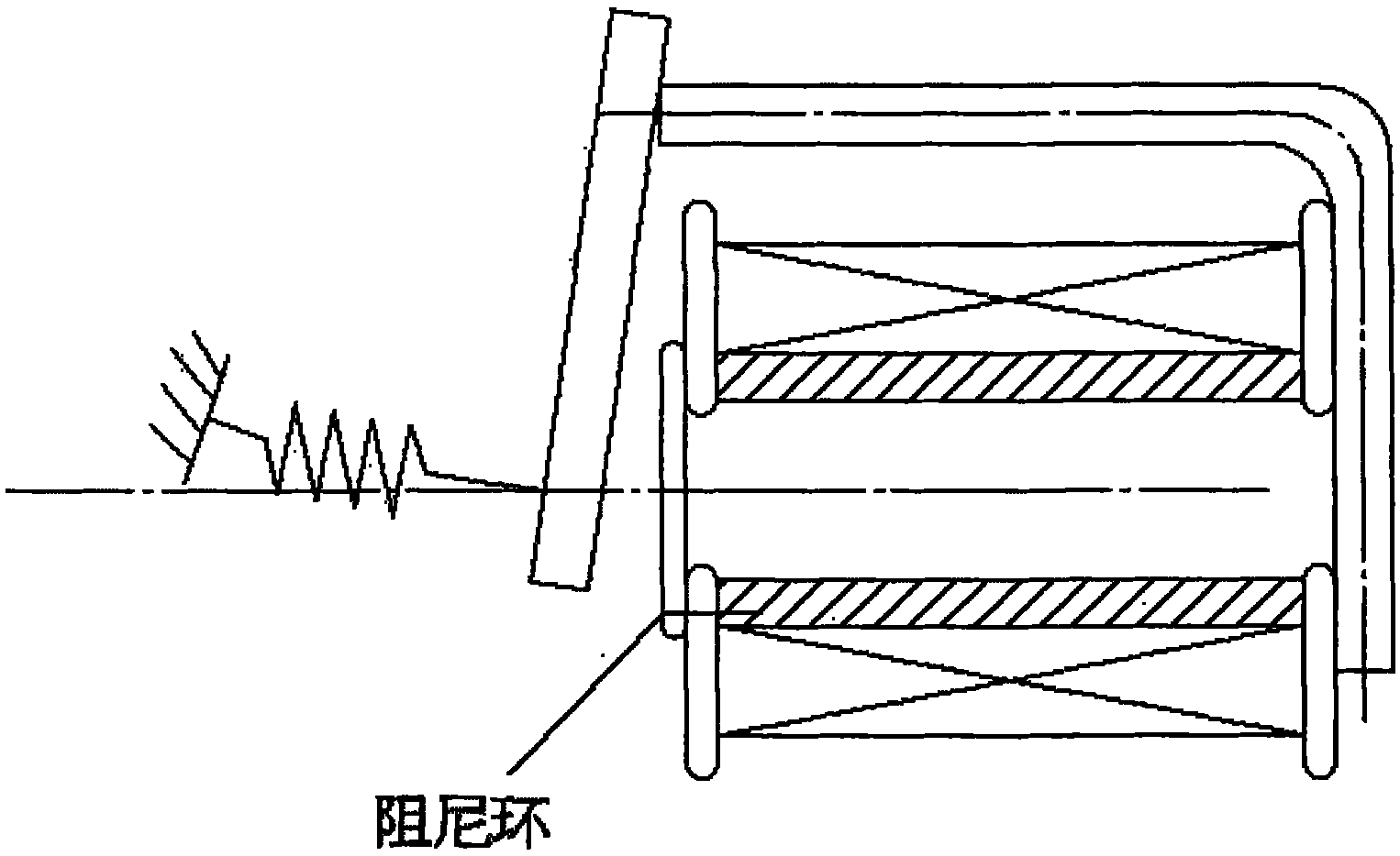
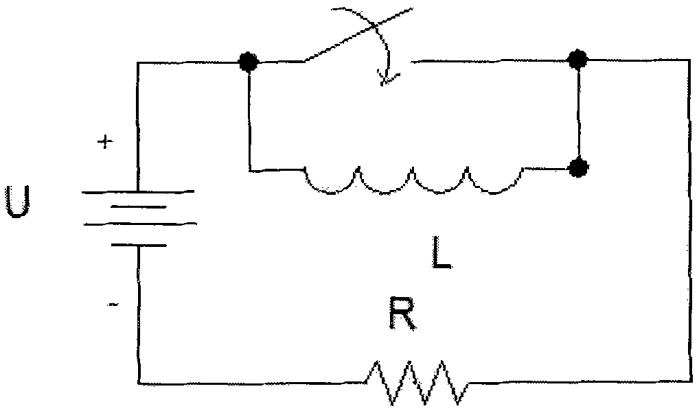
[0031] Such as Figure 7 As shown, a semi-automatic electronically controlled clutch system includes a DC solenoid electromagnet 3, a control circuit 2 for controlling the current on and off of the DC solenoid electromagnet 3, and the control circuit 2 is connected to the transmission lever 1 of the gearbox, the steering wheel 5 and the car key. The sockets are respectively provided with switches, and the armature 301 of the DC coil electromagnet 3 is fixedly connected with the lever 7a at one end of the hydraulic control mechanism 4. The other end of the hydraulic control mechanism 4 is connected with the clutch through the lever 7b. The rated stroke of the armature 301 is 10cm, and the adsorption force of the stop iron 302 of the DC solenoid electromagnet 3 to the armature 301 is 25g (g is the acceleration of gravity) under this rated stroke.

[0032] Such as Figure 8 As shown, the DC spiral tube electromagnet 3 adopts the product MQ8-DC70290 of Wuxi Hydraulic Complete Tec...


PUM


Abstract

The invention discloses a semi-automatic electrically controlled clutch system, comprising a direct-current spiral-tube electromagnet and a control circuit controlling make-break of the current of the direct-current spiral-tube electromagnet. The armature of the direct-current spiral-tube electromagnet is fixedly connected with a lever at one end of a hydraulic operating mechanism, and the other end of the hydraulic operating mechanism is connected with a clutch by the lever. Switches are respectively arranged on a gear lever of a gear box and a steering wheel and at a vehicle key hole on the control circuit. The switch on the steering wheel has three gears such as coupling, separation and semi-linkage. When the driver starts the automobile or shifts gears, the switches on the control circuit are closed so that the clutch and the engine are automatically separated and then recoupled slowly, the electromagnet replaces the clutch pedal on the automobile with manual shift gears, and the separating and coupling speeds of the clutch and the engine can be adjusted by selecting the three gears on the steering wheel, thus greatly simplifying the gear operation of the automobile. Meanwhile, compared with the clutch system of the automobiles with automatic shift gears, the clutch system of the invention effectively lowers the fuel consumption and manufacturing cost and is convenient to maintain.

Description

technical field [0001] The invention relates to the technical field of automobile power transmission, in particular to a semi-automatic electronically controlled clutch system. Background technique [0002] At present, automobiles have become an important means of transportation for people and an indispensable part of human life. At the same time, cars are not just a simple means of transporting goods. With the continuous improvement of the safety and economy of cars, people are more concerned about the driving experience and pursue the driver's control comfort. But now the call for strengthening environmental protection is getting higher and higher, and automobiles have become the target of public criticism due to the emission of CO, NO and other gases harmful to the environment due to the consumption of fossil fuels. With the promulgation of various relevant laws and regulations, people have put forward higher requirements for the design and production of automobiles. ...

Claims


Application Information

Patent Timeline
Patent Type & Authority Applications(China)
IPC IPC(8): F16D27/10F16D27/14
CPCY02T10/76
Inventor 杨华熊树生洪华斌谢煌李伟吴锡江任晓帅
Owner ZHEJIANG UNIV
Learn More