Air-conditioning system using sub-cooler and method for controlling refrigerant flow thereof

A refrigerant flow, air conditioning system technology, applied in subcoolers, refrigerators, refrigeration components, etc., can solve the problems of inability to exert the effect of subcoolers, affect reliability, system hazards, etc., to improve operating efficiency and operation. life, guarantee the use effect, and improve the effect of refrigerant subcooling

Active Publication Date: 2010-11-17
GREE ELECTRIC APPLIANCES INC
View PDF0 Cites 20 Cited by
  • Summary
  • Abstract
  • Description
  • Claims
  • Application Information

AI Technical Summary

Problems solved by technology

[0003] In the multi-line unit using the subcooler, the amount of refrigerant flow through the subcooler plays a key role in the performance of the subcooler. If the refrigerant entering the subcooler is insufficient, the supercooling will not be performed. On the contrary, if too much refrigerant enters the subcooler, it may cause liquid back phenomenon, which will cause harm to the entire system and affect its reliability.

Method used


Image

  • Air-conditioning system using sub-cooler and method for controlling refrigerant flow thereof
  • Air-conditioning system using sub-cooler and method for controlling refrigerant flow thereof
  • Air-conditioning system using sub-cooler and method for controlling refrigerant flow thereof

Examples


Embodiment 1

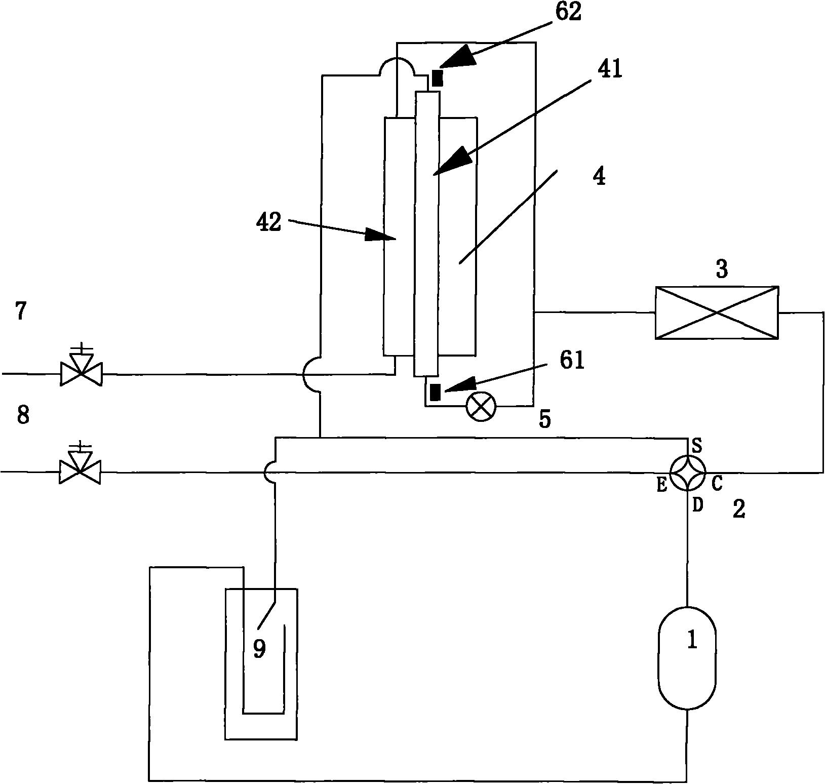
[0032] Such as figure 1 , the first sensor and the second sensor in this embodiment are respectively the first temperature sensor 61 and the second temperature sensor 62, the first temperature sensor 61 is arranged at the inlet end position of the gas pipe 41 of the subcooler, and the second The temperature sensor 62 is located at the outlet end of the gas pipe 41 of the subcooler.

[0033] The refrigerant flow control method in this embodiment is based on the temperature difference control of the gas inlet and gas outlet temperatures on the low-pressure side of the subcooler during the operation of the unit, by controlling the opening of the electronic expansion valve located on the liquid bypass pipeline To realize the control of the refrigerant flow through the low-pressure side of the subcooler; the specific control method is:

[0034] The opening position of the electronic expansion valve is equal to:

[0035] Current opening = original opening + opening change

[0036...

Embodiment 2

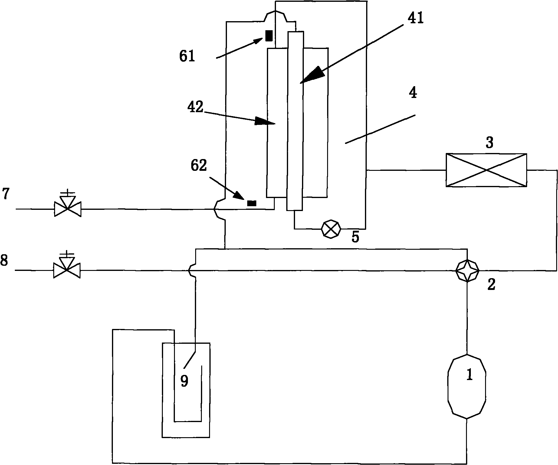
[0042] Such as figure 2 , the first sensor and the second sensor in this embodiment are respectively a first temperature sensor 61 and a second temperature sensor 62, the first temperature sensor 61 is arranged at the inlet end of the liquid pipe 42 of the subcooler, and the first temperature sensor The second temperature sensor 62 is located at the outlet end of the liquid pipe 42 of the subcooler.

[0043] The refrigerant flow control method in this embodiment is based on the temperature difference control of the liquid inlet and liquid outlet temperatures on the high-pressure side of the subcooler during the operation of the unit, by controlling the opening of the electronic expansion valve located on the liquid bypass pipeline To realize the control of the refrigerant flow through the low-pressure side of the subcooler; the specific control method is:

[0044] The temperature T of the refrigerant here is measured in real time by the temperature sensor installed at the in...

Embodiment 3

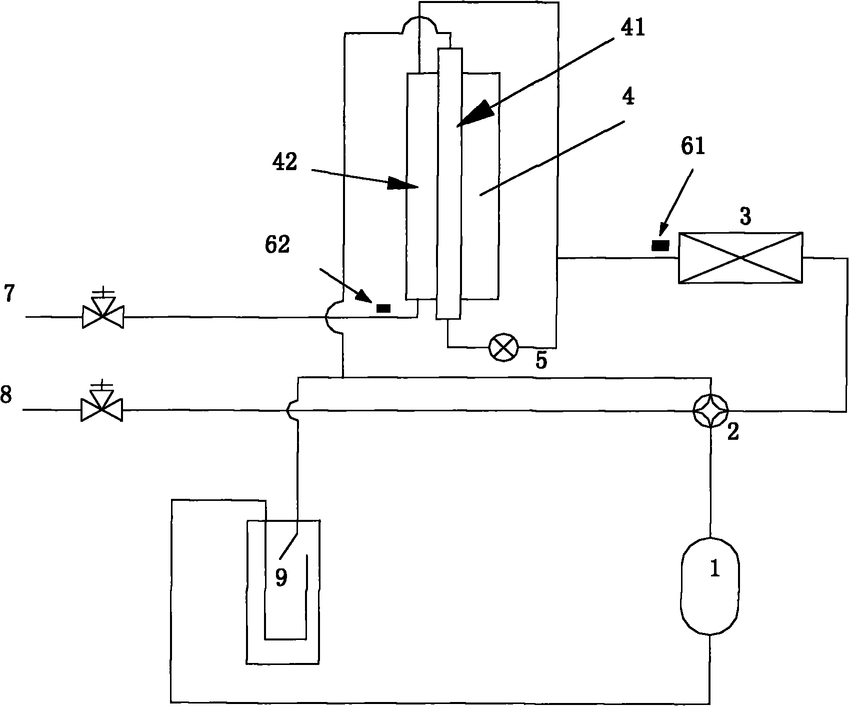
[0052] Such as image 3 , the first sensor and the second sensor in this embodiment are respectively the first temperature sensor 61 and the second temperature sensor 62, the first temperature sensor 61 is set at the second end of the outdoor heat exchanger 3, and the second temperature The sensor 62 is located at the outlet end of the liquid pipe 42 of the subcooler.

[0053] In the control mode of the refrigerant flow in this embodiment, during the operation of the unit,

[0054] During the operation of the unit, based on the temperature difference control of the pipe temperature at the second end of the outdoor heat exchanger and the temperature at the outlet end of the liquid pipe on the high pressure side of the subcooler, it is realized by controlling the opening of the electronic expansion valve located on the liquid bypass pipe Control the refrigerant flow through the low-pressure side of the subcooler; the specific control method is:

[0055] The opening position of...


PUM


Abstract

The invention provides an air-conditioning system using a sub-cooler and a method for controlling refrigerant flow thereof. The effect of the sub-cooler is exerted better by controlling the refrigerant flow on the low-pressure side of the sub-cooler so as to ensure that proper refrigerant is provided for cyclic operation when the system runs, improve the running efficiency and prolong the service life of a unit and ensure the using effect of a user. The air-conditioning system comprises a first sensor and a second sensor; the first sensor and the second sensor are arranged at different positions of a refrigerating system circulating passage; a controller comprises an operation result module and an output module; the operation result module calculates the refrigerant flow according to the data acquired by the first sensor and the second sensor, and converts the refrigerant flow into opening instruction of an electronic expansion valve; and the output module controls the opening of the electronic expansion valve according to the opening instruction of the electronic expansion valve.

Description

technical field [0001] The invention belongs to the technical field of air conditioning, and in particular relates to an air conditioning system using a supercooler and a method for controlling the flow of refrigerant thereof. Background technique [0002] The structure, connection relationship, function and working principle of the subcooler in the air conditioning system: the refrigerant coming out of the outdoor heat exchanger is a high-temperature and high-pressure liquid, and then divided into two paths, and the refrigerant in one path enters the subcooling The refrigerant in the other path is throttled by the electronic expansion valve, and its pressure and temperature will be further reduced, and then enter the air pipe of the subcooler. The refrigerant in the air pipe of the subcooler absorbs the refrigerant outside the pipe (that is, the The heat of the refrigerant in the liquid pipe) evaporates and becomes refrigerant gas. And because the refrigerant in the liquid...

Claims


Application Information

Patent Timeline
Patent Type & Authority Applications(China)
IPC IPC(8): F25B13/00F25B41/06F25B40/02F25B49/02
CPCY02B30/72Y02B30/70
Inventor 张龙刘煜宋培刚黄春肖翰生杨智峰
Owner GREE ELECTRIC APPLIANCES INC
Why Eureka
Try Eureka