Hall switch circuit with temperature compensation

A Hall switch and circuit technology, which is applied in improving amplifiers to reduce temperature/power supply voltage changes, DC-coupled DC amplifiers, and using electromagnetic/magnetic devices to transmit sensing components, etc. Difficult to guarantee, etc.

Active Publication Date: 2010-11-17
SHANGHAI ORIENT CHIP TECH CO LTD
View PDF10 Cites 21 Cited by
  • Summary
  • Abstract
  • Description
  • Claims
  • Application Information

AI Technical Summary

Problems solved by technology

This method makes the second-order characteristics more difficult to control; considering the drif

Method used


Image

  • Hall switch circuit with temperature compensation
  • Hall switch circuit with temperature compensation
  • Hall switch circuit with temperature compensation

Examples


Embodiment Construction

[0021] The following is attached Figure 3-4 The present invention is further described:

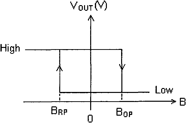
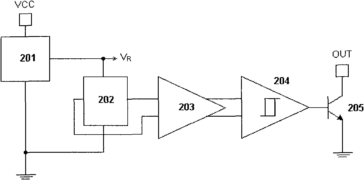
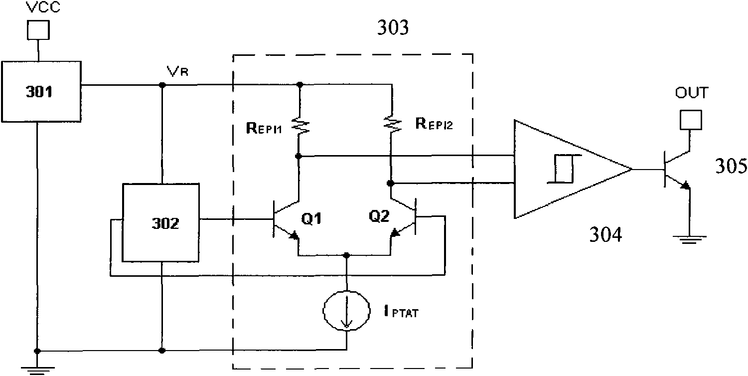
[0022] refer to image 3 , the Hall switch circuit of the present invention includes a voltage regulator 301 with a constant temperature, a Hall sensing chip 302 connected between the output of the voltage regulator 301 and the ground wire, and two input terminals connected to the Hall sensing chip 302 respectively. Hall voltage differential amplifier 303 , a hysteresis comparator 304 whose hysteresis width is constant to temperature connected to the output terminal of the Hall voltage differential amplifier, and an output unit 305 connected to the output terminal of the hysteresis comparator 304 . The Hall voltage differential amplifier consists of a current source proportional to absolute temperature (PTAT) I PTAT , two NPN transistors Q 1 and Q 2 Composed of a differential input pair and a resistor R of the same type of material as the Hall sensor EPI1 , R EPI2 constitute. wher...


PUM


Abstract

The invention relates to a Hall switch circuit with temperature compensation, comprising a voltage stabilizer, a Hall induction sheet, a Hall voltage difference amplifier, a hysteresis comparator and an output unit, wherein the Hall induction sheet is connected between the output and an earth wire of the voltage stabilizer; two input ends of the Hall voltage difference amplifier are respectively connected with the Hall induction sheet; the hysteresis comparator is connected with the output end of the Hall voltage difference amplifier; and the output unit is connected with the input end of the hysteresis comparator. The Hall switch circuit is characterized in that the Hall voltage difference amplifier comprises a difference input pair, a current source and a load resistor, wherein the difference input pair consists of two transistors; the current source offsets the difference input pair and is directly proportional to absolute temperature; and the load resistor is respectively in series connected with the transistors of the difference input pair and is made from materials the same as that of the Hall induction sheet. The Hall switch circuit can eliminate the influence of microhenry temperature coefficient without special requirement for a process and is well controlled.

Description

technical field [0001] The invention relates to a Hall switch circuit, in particular to a Hall switch circuit with temperature compensation. Background technique [0002] The principle of the Hall effect is: for a suitable Hall material, if V is energized along its X direction R , if a magnetic field B is applied in the Y direction, a voltage V will appear in the Z direction H , V H Called the Hall voltage, it is related to the magnetic field B, the voltage V R The relationship with the material itself is [0003] V H = μ H BV R W L σ ( L W ) - - - ( 1 ) [0004] Where L, W are the length and width of the Hall material, is the geometry correction factor, μ H is the Hall mobility. [0005]...

Claims


Application Information

Patent Timeline
IPC IPC(8): G01D5/12H03F1/30H03F3/45
Inventor 罗立权张良吴玉江
Owner SHANGHAI ORIENT CHIP TECH CO LTD
Why Eureka
Try Eureka