Antenna equipment shared by multiple systems

An antenna device, multi-system technology, applied in antennas, independent non-interacting antenna combinations, antenna unit combinations with different polarization directions, etc., can solve the problems of signal loss, shortage of antenna resources, etc., to avoid signal loss , the effect of saving sky resources

Inactive Publication Date: 2010-11-17
CHINA MOBILE COMM GRP CO LTD
View PDF0 Cites 18 Cited by
  • Summary
  • Abstract
  • Description
  • Claims
  • Application Information

AI Technical Summary

Problems solved by technology

[0004] The embodiment of the present invention provides a multi-system shared antenna device to solve the problem of shortage of antenna resources in the existing multi-system antenna fusion technology and the problem of signal loss caused by the introduction of a router

Method used


Image

  • Antenna equipment shared by multiple systems
  • Antenna equipment shared by multiple systems
  • Antenna equipment shared by multiple systems

Examples


Embodiment Construction

[0012] Aiming at the problems existing in the prior art, the embodiment of the present invention adopts a common antenna mode, and by setting the TD system antenna array and the LTE (or GSM) antenna array on one antenna device, the TD system and the LTE (or GSM) system share the antenna. .

[0013] Embodiments of the present invention will be described in detail below in conjunction with the accompanying drawings.

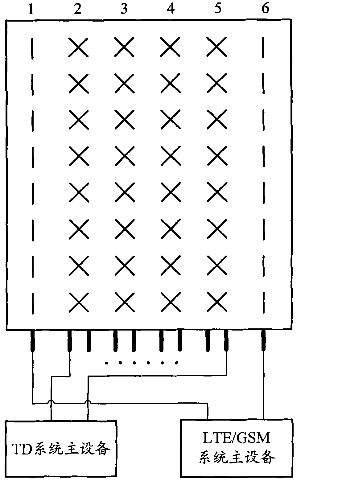
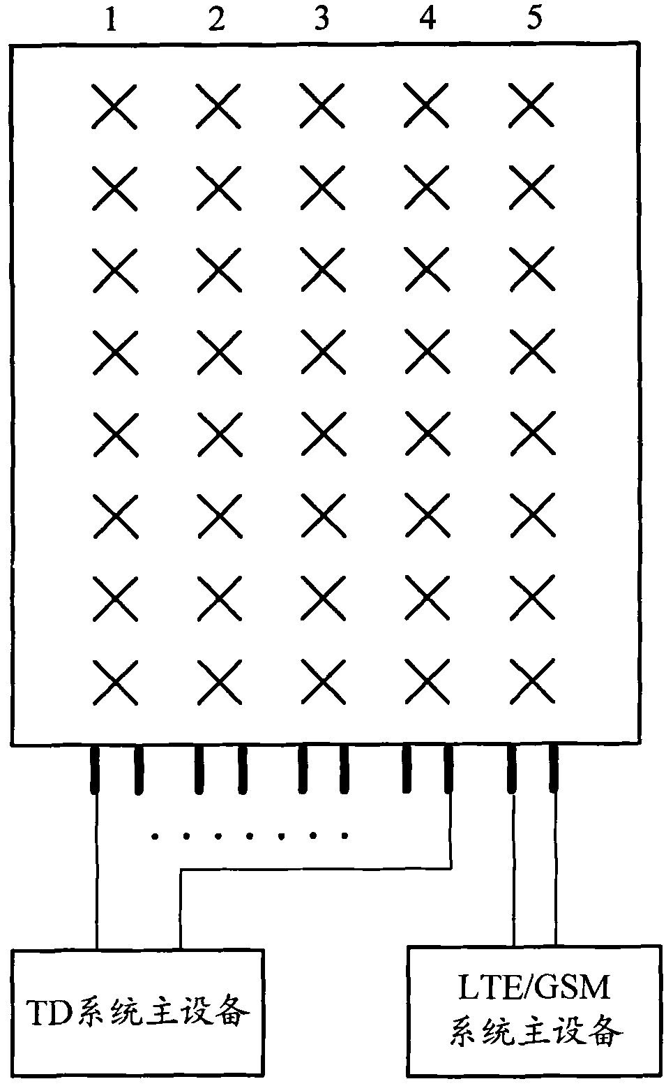
[0014] see Figure 2A and Figure 2B , is a schematic diagram of the array layout of the antenna device provided by the embodiment of the present invention. Figure 2A The antenna device shown takes an 8-antenna antenna device as an example. The array of the antenna device is a 6×8 array, that is, the layout of the array elements in the array is 8 rows and 6 columns, and each column is sequentially numbered as 1, 2, 3, 4, 5, 6 columns. in:

[0015] The elements in the 2nd, 3rd, 4th, and 5th columns are radiating units designed based on the AB frequency band (1...


PUM


Abstract

The invention discloses antenna equipment shared by multiple systems, which aims to solve the problems of signal loss caused by the introduction of a combiner in the conventional multi-system antenna fusion technology and roof resource shortage. In an antenna array of the antenna equipment, a part of the array is used for receiving and transmitting signals of a fourth generation or second generation mobile communication system, and antenna ports corresponding to the array are used for connecting master devices of the fourth generation or second generation mobile communication system; and in the antenna array of the antenna equipment, the rest part of the array is used for receiving and transmitting signals of a third generation mobile communication system, and antenna ports corresponding to the array are used for connecting master devices of the third generation mobile communication system.

Description

technical field [0001] The invention relates to the field of mobile communication, in particular to an antenna device that can be shared by multiple mobile communication systems. Background technique [0002] With the development of mobile communication technology, in addition to the second generation global system for mobile communication (2G GSM) network and the third generation time division synchronous code division multiple access technology (3G TD-SCDMA) network under construction, there will also be Fourth generation Time Division Long Term Evolution (4G TD-LTE) network. In this case, there will inevitably be a network development in which multiple communication systems coexist. The current three communication systems all have independent antenna feeder systems, and the frequency bands used are also very different. However, at present, because multiple operators have networks of 2G and 3G standards, and considering the subsequent evolution, the number of antenna fee...

Claims


Application Information

Patent Timeline
Patent Type & Authority Applications(China)
IPC IPC(8): H01Q21/28H01Q21/24H01Q3/34
Inventor 马欣
Owner CHINA MOBILE COMM GRP CO LTD
Why Eureka
Try Eureka