
Method and device for realizing backbone optical fiber protection in Ethernet passive optical network

A passive optical network and optical fiber protection technology, applied in the field of passive optical network, can solve the problem that the service recovery time cannot meet the carrier-class requirements, the ONU is disconnected, etc., so as to shorten the recovery time, enhance the reliability, and improve the performance. Effect

Active Publication Date: 2010-11-17
ZTE CORP
View PDF0 Cites 25 Cited by
  • Summary
  • Abstract
  • Description
  • Claims
  • Application Information

AI Technical Summary

Problems solved by technology

If the MPCP counter of the ONU changes more than 8 TQ, it will cause the ONU to go offline and need to re-register. At this time, the service recovery time cannot meet the carrier-grade requirement of 50ms

Method used


Image

  • Method and device for realizing backbone optical fiber protection in Ethernet passive optical network
  • Method and device for realizing backbone optical fiber protection in Ethernet passive optical network
  • Method and device for realizing backbone optical fiber protection in Ethernet passive optical network

Examples


Embodiment Construction

[0045] The present invention will be described in detail below with reference to the drawings and specific embodiments.

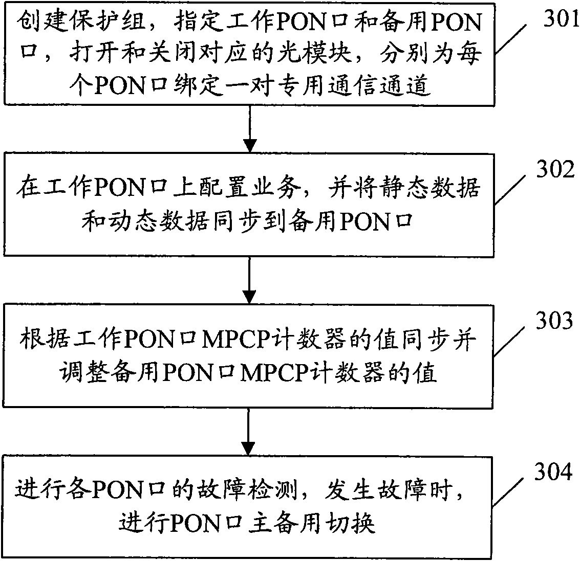
[0046] The following boards refer to EPON line cards. One EPON line card can have one or more PON ports. If it is the protection between PON ports on the same line card, it is called in-board protection. If it is one of different EPON line cards Inter-board PON port protection is inter-board protection. The specific embodiment described below takes the creation of an inter-board protection group as an example to illustrate the implementation process of the backbone optical fiber protection of the present invention. The implementation process of the method for implementing the backbone optical fiber protection of the EPON of the present invention is as follows: image 3 As shown, including the following steps:

[0047] Step 301: Create a protection group. The OLT side core control board designates a working PON port and a backup PON port, and binds a pair of dedi...


PUM


Abstract

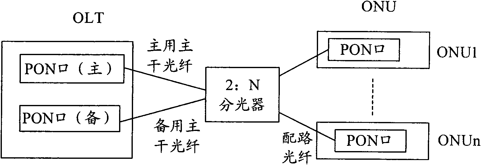
The invention discloses a method for realizing backbone optical fiber protection in an Ethernet passive optical network (EPON), which comprises that: master / backup PON ports are respectively bond with a pair of dedicated communication channels; service is configured at a working PON port, and static data and dynamic data are synchronized to the backup PON port; a value of an MPCP counter of the backup PON port is synchronized and adjusted according to a value of a multi-point control protocol MPCP counter of the working PON port; and fault monitoring is carried out, and the master / backup PON port switching is carried out once a fault happens. The invention also discloses a device for realizing backbone optical fiber protection in an Ethernet passive optical network. Through the method andthe device, the PON ports are bond with the dedicated communication channels, so quick communication between the master / backup PON ports can be realized; and by adjusting the MPCP counter of the backup PON port, the EPON does not need to re-register ONU during protection switching, the service restoration time is shortened, and the protection switching performance is improved.

Description

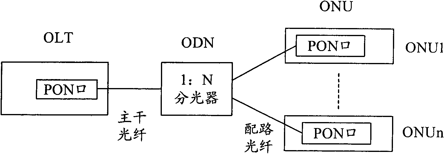
Technical field [0001] The present invention relates to passive optical network (PON: Passive Optical Network) technology, in particular to a method and device for realizing backbone optical fiber protection in an Ethernet Passive Optical Network (EPON: Ethernet Passive Optical Network) system. Background technique [0002] EPON is a new type of optical fiber access network technology, adopting point-to-multipoint structure, passive optical fiber transmission, and providing multiple services on Ethernet. EPON is composed of an optical line terminal (OLT: Optical Line Terminal) on the central office side, an optical network unit (ONU: Optical Network Unit) on the user side, and an optical distribution network (ODN: Optical Distribution Network). EPON uses PON technology at the physical layer, Ethernet protocol at the link layer, and uses the PON topology to achieve Ethernet access. Therefore, EPON combines the advantages of PON technology and Ethernet technology: low cost, high b...

Claims


Application Information

Patent Timeline
IPC IPC(8): H04B10/08H04B1/74H04J3/06
CPCH04Q2011/0081H04Q11/0067H04Q2011/0088H04B10/25H04B10/27
Inventor 孙伟平陆建鑫谢云鹏
Owner ZTE CORP
Learn More