Micro-hydro generator

A hydroelectric power generation device and miniature technology, applied in the directions of injection devices, injection devices, engine components, etc., can solve the problems of large fan blade resistance and affect power generation efficiency, and achieve the effect of improving power generation efficiency, ensuring service life and high power generation efficiency

Active Publication Date: 2010-11-24
ZHUHAI EDISON ECOTECH CORP CO LTD
View PDF6 Cites 2 Cited by
  • Summary
  • Abstract
  • Description
  • Claims
  • Application Information

AI Technical Summary

Problems solved by technology

[0004] For this reason, the technical problem to be solved by the present invention is that in the micro hydroelectric power generation device in the prior art, since the water in the cavity will flow back into the water inlet cavity to form backflow water, the resistance when the fan blade rotates is relatively large, Problems that affect power generation efficiency, thus proposing a micro hydroelectric power generation device that reduces the resistance of backflow water to the rotor and improves power generation efficiency

Method used


Image

  • Micro-hydro generator
  • Micro-hydro generator
  • Micro-hydro generator

Examples


Embodiment Construction

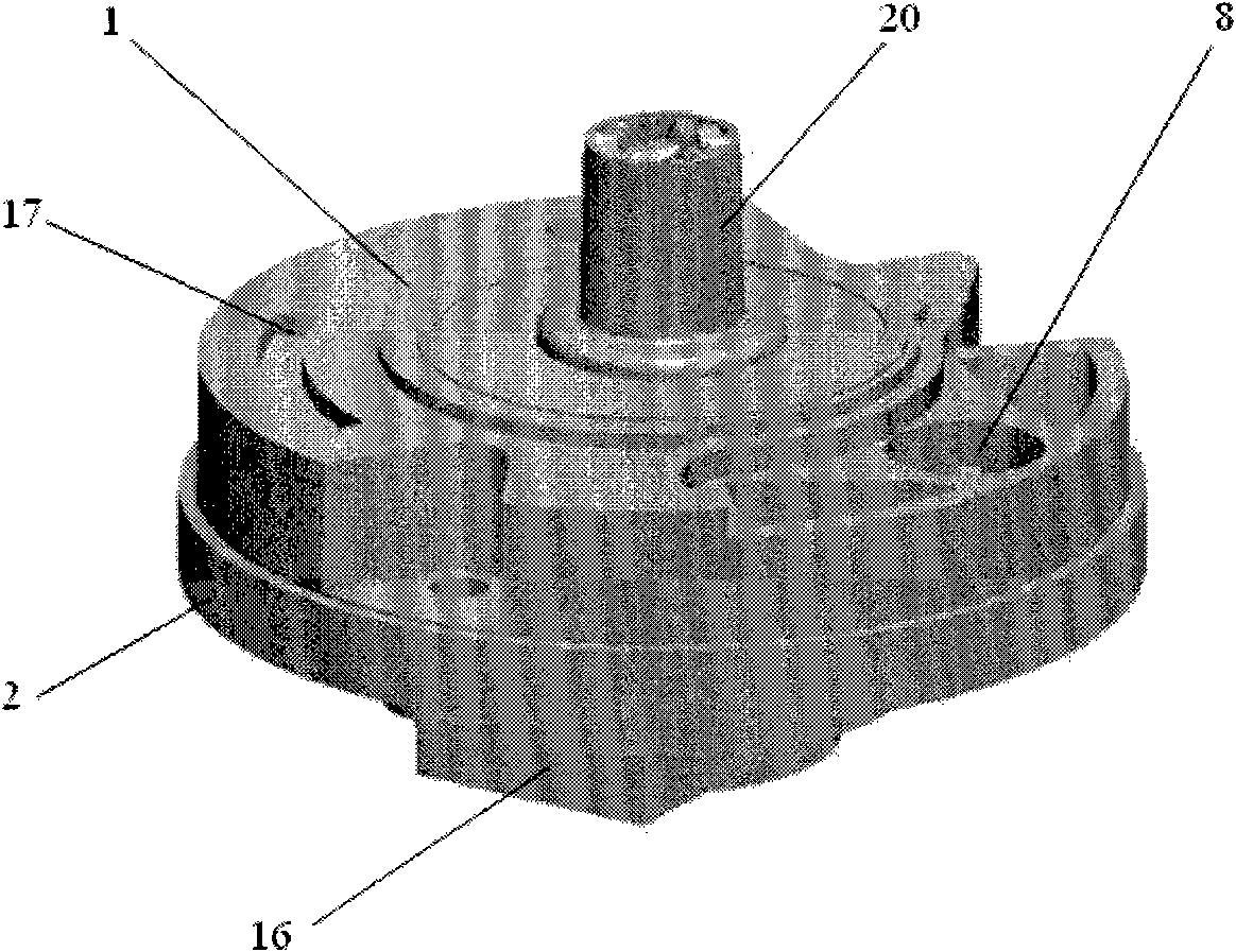
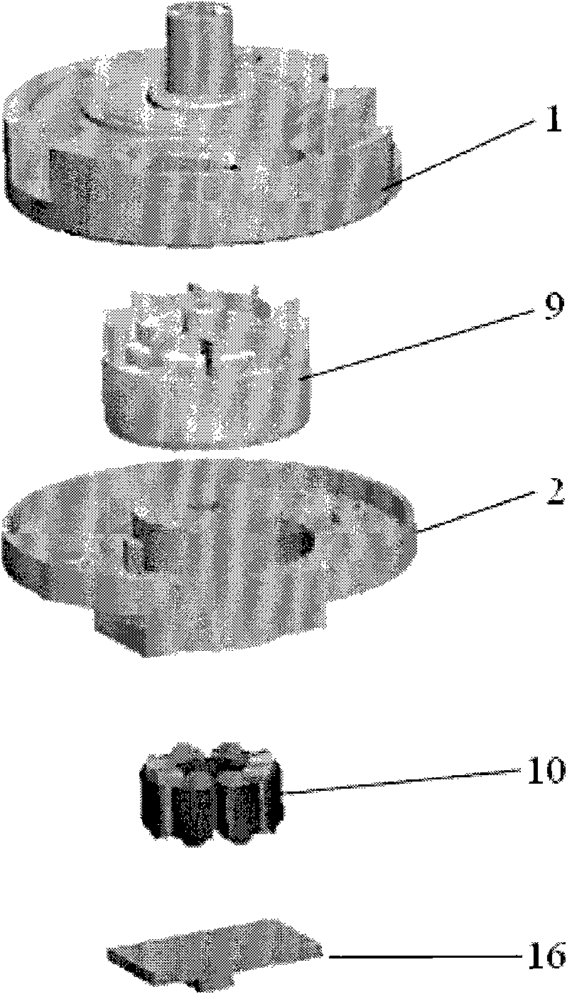
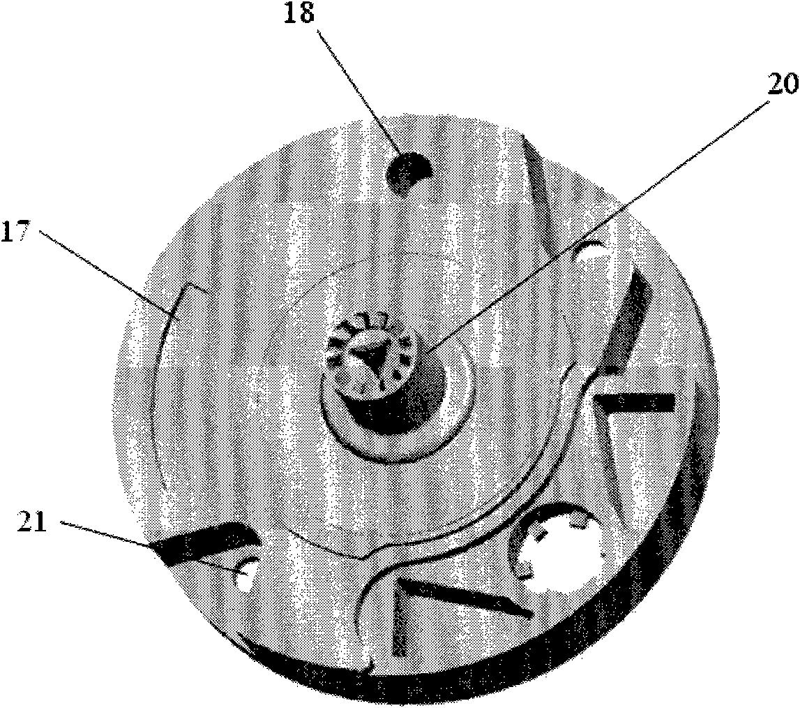
[0044] figure 1 , figure 2 A specific implementation of the micro-hydroelectric power generation device according to the present invention is given. A micro-hydropower generation device includes an upper cover 1 and a lower cover 2, wherein the upper cover 1 is formed with a water storage cavity 3 and a rotor cavity 4. A common wall 5 is provided between the rotor cavity 4 and the water storage cavity 3, and the wall 5 is provided with a flushing port connecting the water storage cavity 3 and the rotor cavity 4, where , Three flushing ports 6, 61, 62 are set, evenly arranged on both sides and the middle of the wall 5 shared by the water storage cavity 3 and the rotor cavity 4, such as Figure 4 Shown. The flushing openings 6, 61, 62 are incisions that deviate from the radial direction of the rotor 9, so as to ensure that the impulse of the water entering the rotor cavity 4 through the three flushing openings performs better on the rotor 9 Speed ​​up and reduce the loss of wate...


PUM


Abstract

The invention discloses a micro-hydro generator, which comprises an upper cover and a lower cover. A water storage cavity and a rotor cavity are formed on the upper cover; a shared wall is formed between the rotor cavity and the water storage cavity; the wall is provided with a flushing port communicated with the water storage cavity and the rotor cavity; a water inlet is formed on the lower cover and used for injecting water into the water storage cavity; a water outlet is formed on the upper cover and positioned in the rotor cavity and is opposite to the wall; a rotatable rotor is arranged in the rotor cavity; the lower cover is provided with a stator matched with the rotor; and the rotor cavity has a shape of which the cross sectional area is gradually reduced from the wall to the water outlet. The micro-hydro generator solves the technical problems that a blade undergoes relatively large resistance and the generation efficiency is influenced because water in an accommodating cavity flows back to a water inlet cavity and forms flowback water in the micro-hydro generator of the prior art; besides, the micro-hydro generator is suitable for showers, faucets and the like.

Description

Technical field [0001] The invention relates to a micro-hydroelectric power generation device, in particular to a micro-generator for power generation from running water. Background technique [0002] Hydropower usually refers to the use of rivers, lakes and other high-place water flowing to low places, the potential energy contained in them is converted into the kinetic energy of the water turbine, and then the water turbine drives the generator to generate electricity. As flowing tap water, it also has kinetic energy, so it can also be used to generate electricity. The electric energy generated by this micro-hydroelectric power generation device can be used in products such as LED showers, LED faucets, or luminous showers for lighting or LED indications or LED color changes. [0003] Chinese patent document CN201304374Y discloses a light-emitting shower head, including a handle, a water inlet is arranged in the handle, and a cavity is connected to the water inlet, and the cavity...

Claims


Application Information

Patent Timeline
Patent Type & Authority Applications(China)
IPC IPC(8): F03B13/00B05B1/18
Inventor 陈孝林
Owner ZHUHAI EDISON ECOTECH CORP CO LTD
Why Eureka
Try Eureka