
Multi-wave wave field separation and synthesis method and system

A synthesis method and vector wave field technology, which can be used in measurement devices, instruments, scientific instruments, etc., to solve problems such as loss of effective seismic wave data, difficulty in solving wave vector directions, and inability to achieve wave field separation.

Active Publication Date: 2010-11-24
INST OF GEOLOGY & GEOPHYSICS CHINESE ACAD OF SCI +1
View PDF8 Cites 27 Cited by
  • Summary
  • Abstract
  • Description
  • Claims
  • Application Information

AI Technical Summary

Problems solved by technology

At a certain moment, the longitudinal wave and the shear wave have completely different wave vector directions, and theoretically they are both linearly polarized; but in order to preserve the anisotropy information of the reservoir, the actual multicomponent seismic data acquisition uses a single point without combination In the receiving mode, multi-component seismic data often have a low signal-to-noise ratio, which makes the vibration trajectory of seismic waves in a certain time window chaotic, which makes it difficult to solve the wave vector direction
[0009] To sum up, after wave field separation in the existing technology, although seismic wave data after suppressing noise can be obtained to a certain extent, it cannot achieve complete wave field separation and cannot obtain true amplitude, which leads to the fact that part of the seismic wave is effectively Data loss, resulting in insufficient accuracy in seismic data analysis

Method used


Image

  • Multi-wave wave field separation and synthesis method and system
  • Multi-wave wave field separation and synthesis method and system
  • Multi-wave wave field separation and synthesis method and system

Examples


Embodiment Construction

[0040] The implementation of the present invention will be described in detail below in conjunction with the drawings and examples, so that the realization process of how to use technical means to solve technical problems and achieve technical effects in the present invention can be fully understood and implemented accordingly.

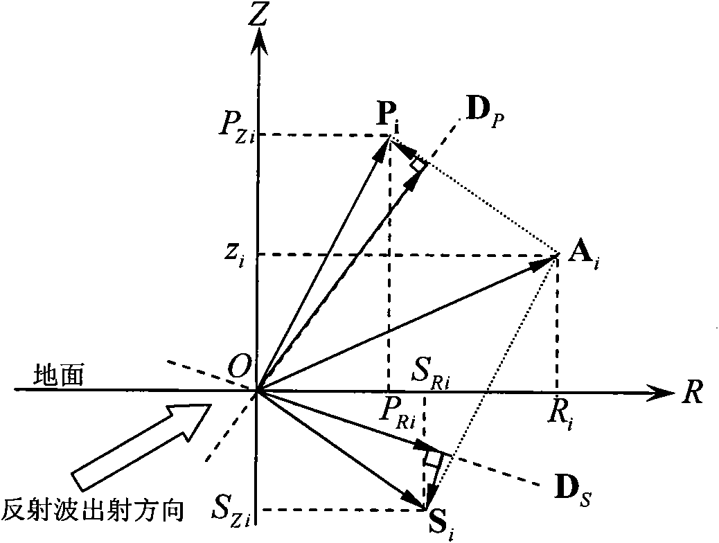
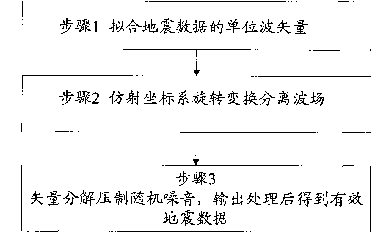
[0041] The core concept of the present invention is: vector superposition of all the wave vectors of the longitudinal wave / shear wave in the quadrant where the longitudinal wave / shear wave is located in a certain time window, and obtain the longitudinal wave / shear wave unit wave vector according to the vector obtained after the superposition; for a certain time window At one moment, decompose the longitudinal wave vector and the shear wave vector of the seismic wave at this moment in the R and Z axis directions for the R-O-Z coordinate system, and then form a non-orthogonal affine coordinate system with the directions of the longitudinal wave vector and...


PUM


Abstract

The invention discloses a multi-wave wave field separation and synthesis method and a system. The method comprises the following steps: carrying out vector superposition on all wave vectors within a quadrant in which longitudinal wave / transverse waves are positioned in a certain time window; obtaining longitudinal wave / transverse wave unit wave vectors based on the superposed vector; at a moment in the time window, separating longitudinal wave / transverse wave vector along the R axis / Z axis respectively, forming an affine coordinate system in direction of the longitudinal wave / transverse wave vector, and converting the separated longitudinal wave / transverse wave vector to the affine coordinate system based on an included angle between the longitudinal wave / transverse wave vector and the R axis and an included angle between the longitudinal wave / transverse wave vector and the Z axis; and based on the unit wave vector, separating the longitudinal wave / transverse wave vector at a moment in the time window to obtain the parallel parts of the longitudinal wave / transverse wave vector and relevant unit wave vector under the affine coordinate system for output. The invention can separate the wave fields of the longitudinal wave vector and the transverse wave vector, recover the vector amplitude of the longitudinal wave / transverse wave, suppress noise, and improve accuracy of earthquake data analysis, thereby meeting need of earthquake data analysis and explanation.

Description

technical field [0001] The invention belongs to the field of seismic data analysis, and in particular relates to a method and system for separating and synthesizing multi-wave wave fields. Background technique [0002] For onshore multi-component seismic exploration, due to the existence of the low-velocity zone, it can be assumed that the vertical component mainly receives longitudinal waves, and the horizontal component mainly receives shear waves. However, this assumption is difficult to establish in the shallow area of ​​the low-velocity zone, especially when the offset is large, it will produce an effect called "mode leakage", that is, both the horizontal component and the vertical component receive the P-wave and S-wave Partially polarized projection. Suppressing the effect of "mode leakage", that is, the separation of longitudinal and shear wave fields, is an important aspect of multicomponent seismic data processing, and it is also a difficult point. [0003] There...

Claims


Application Information

Patent Timeline
IPC IPC(8): G01V1/30G01V1/28
CPCG01V2210/48G01V2210/586G01V1/286
Inventor 王赟芦俊
Owner INST OF GEOLOGY & GEOPHYSICS CHINESE ACAD OF SCI
Learn More