Automatic stereoscopic display device

An automatic stereoscopic display and display panel technology, applied in stereoscopic systems, identification devices, static indicators, etc., can solve the problems of being able to be seen by the right eye, visual fatigue of the observer, and affecting the display quality of 3D display images, so as to reduce light leakage phenomenon, reducing visual fatigue, and avoiding image crosstalk

Active Publication Date: 2010-11-24
KUSN INFOVISION OPTOELECTRONICS
View PDF7 Cites 17 Cited by
  • Summary
  • Abstract
  • Description
  • Claims
  • Application Information

AI Technical Summary

Problems solved by technology

The left image 1 and the right image 2 are alternately arranged on the display screen, and the backlight ( figure 1 not shown in ) emits light to illuminate the left image 1 and the right image 2 on the display screen, then through the refraction of the lens array 5 (composed of a plurality of lens units) arranged in front of the display screen, the left image 1 is illuminated The light rays and the light rays illuminating the right image 2 are mainly divided into light rays 3 emitted along the first orientation and rays 4 emitted along the second orientation, and the rays 3 emitted along the first orientation and rays 4 emitted along the second orientation are respectively Enter the left eye and the right eye of the observer; but, due to the limitations of the current autostereoscopic display technology, there will still be some light rays such as the leakage light that illuminates the left image 1 through the lens array 5 (3' in the figure) roughly along the The light leaking into the right eye in the second orientation, or the light leakage light (4' in the figure) that illuminates the right image 2 is roughly incident in the left eye along the first orientation, and this light leakage is called image crosstalk (crosstalk). The resulting problem is that part of the left image can be seen by the right eye and vice versa
Similarly, for the autostereoscopic display device of the barrier type, this phenomenon cannot be avoided
This seriously affects the display quality of the 3D display screen, causing serious visual fatigue to the observer

Method used


Image

  • Automatic stereoscopic display device
  • Automatic stereoscopic display device
  • Automatic stereoscopic display device

Examples


Embodiment Construction

[0023] In order to make the above-mentioned objectives, features and advantages more obvious and understandable, the specific embodiments of the present invention will be described in detail below with reference to the accompanying drawings.
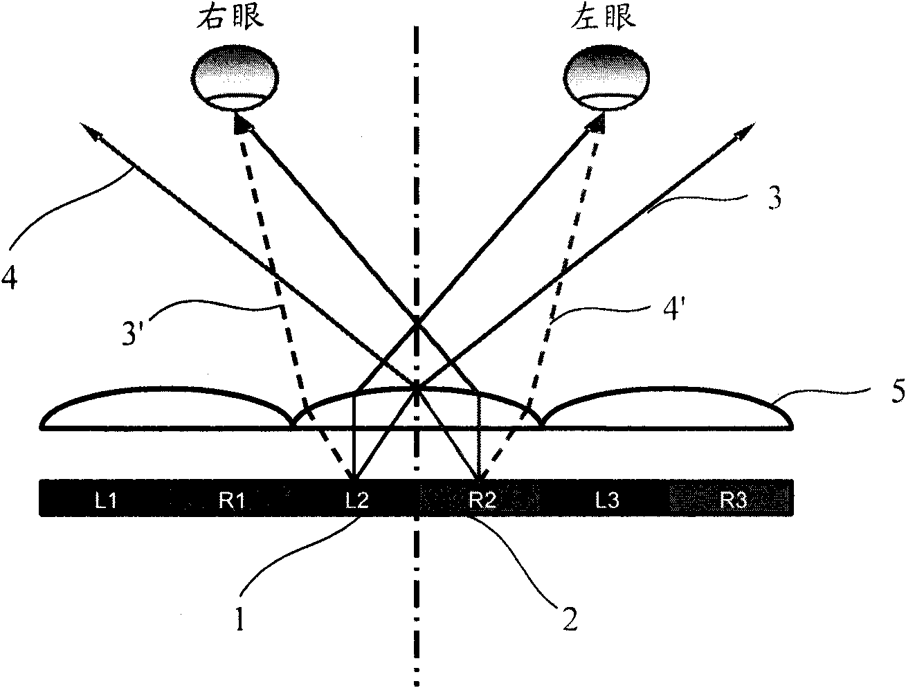
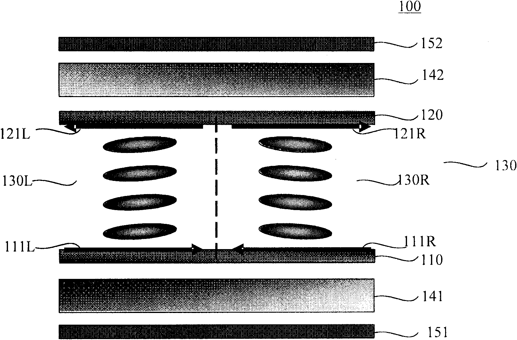
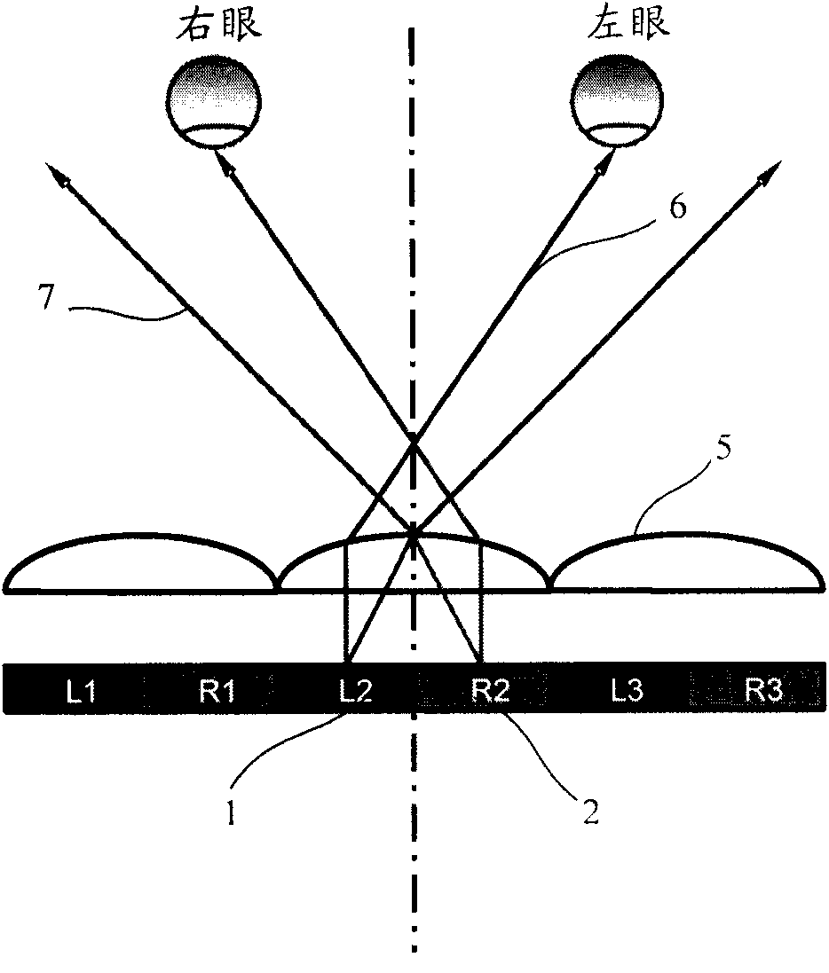
[0024] The core idea of ​​the present invention is to divide each pixel unit in the autostereoscopic display device into two domains, namely into a left sub-pixel unit and a right sub-pixel unit, where the left sub-pixel unit and the right sub-pixel unit are The alignment of the liquid crystal molecules is opposite, so the opposite pretilt angle (pretilt) is generated. When an appropriate voltage is applied to the liquid crystal layer, the liquid crystal molecules are deflected, so that the left image in the left sub-pixel unit is irradiated by light and mainly enters the observation At the same time, the right image in the right sub-pixel unit is irradiated by light and mainly enters the observer’s right eye. When the left and right sub-pix...


PUM

PropertyMeasurementUnit
angleaaaaaaaaaa
refractive indexaaaaaaaaaa

Abstract

The invention discloses an automatic stereoscopic display device. The device comprises a display panel and a back light, wherein the display panel comprises an upper substrate and a lower substrate which are oppositely arranged, and a liquid crystal layer sealed between the upper substrate and the lower substrate; and the liquid crystal layer consists of a plurality of liquid crystal molecules; the back light is used for providing light ray for the display panel; the display panel comprises a plurality of pixel units, and each pixel unit comprises a first sub-pixel unit and a second sub-pixel unit; the liquid crystal molecules positioned in the first sub-pixel unit are oppositely matched with those positioned in the second sub-pixel unit; and the light ray exists along a first direction after passing through the liquid crystal molecules positioned in the first sub-pixel unit in the display panel, and exists along a second direction after passing through the liquid crystal molecules positioned in the second sub-pixel unit. The device can reduce image crosstalk generated by a display picture.

Description

Technical field [0001] The present invention relates to the technical field of three-dimensional (3D) stereoscopic display, in particular to an autostereoscopic display device capable of reducing image crosstalk. Background technique [0002] With the increase in the size of TV sets and the increase in resolution, high definition television (HDTV: High Deefnition Television) technology has become a goal that people continue to pursue in order to provide viewers with more realistic pictures. [0003] As we all know, the real world is a three-dimensional world, and the human three-dimensional visual effect mainly relies on two human eyes, that is, the surrounding environment seen by the human eyes actually has a slight deviation in direction. The deviation of the distance between the pupils of the two eyes or the pupils of the two eyes is different. The average interpupillary distance of an adult is about 65 mm, which makes two images with slight differences in viewing angles formed...

Claims


Application Information

Patent Timeline
Patent Type & Authority Applications(China)
IPC IPC(8): G02F1/1337G02B27/22G02F1/133G02F1/1335H04N13/00H04N13/04G09F9/35G02B30/28
CPCG02F2001/133757G02F1/134363G02F1/133753H04N13/0402G02B27/2214H04N13/302G02F1/133757G02B30/28G02B30/27
Inventor 陈超平
Owner KUSN INFOVISION OPTOELECTRONICS
Why Eureka
Try Eureka