Probe scanning device of reactor pressure vessel inspection machine

A pressure vessel and scanning device technology, which is applied in the fields of reactors, nuclear reactor monitoring, nuclear power generation, etc., can solve the problems that affect the comprehensive scanning of the area to be tested, the movement range of the ultrasonic probe is blocked, and the test results are unreliable, so as to ensure comprehensive scanning. Check, tightly coupled, ensure reliability and accuracy

Active Publication Date: 2010-11-24
CGNPC INSPECTION TECH +2
View PDF4 Cites 29 Cited by
  • Summary
  • Abstract
  • Description
  • Claims
  • Application Information

AI Technical Summary

Problems solved by technology

[0002] The lower part of the nuclear reactor pressure vessel is welded by a cylindrical body 100 and a hemispherical lower head 200, such as figure 1 As shown, therefore, there is a weld 300 at the connection between the two under the pressure vessel. According to the relevant inspection specifications of nuclear power plants, the area of ​​50mm on both sides of the weld ( image 3 (shown in the shaded part in the middle) for flaw detection inspection. At the same time, the surfacing layer on the surface also needs to be scanned with the weld as the center line and 250 mm on both sides. In the prior art, there are ultrasonic principles for detection The principle of the inspection machine is to extend the probe into the bottom of the pressure vessel for scanning. Since the area to be scanned is a spherical surface, the installation method of the existing ultrasonic probe cannot ensure the close coupling between the probe and the spherical arc surface, resulting in unreliable detection results. Moreover, at the bottom of the pressure vessel, there are a plurality of penetrating pieces 400 erected on different horizontal levels, and the top penetrating piece 400 is close to the area to be tested, so that the movement range of the ultrasonic probe is blocked, thus affecting the comprehensive scanning of the area to be tested.

Method used


Image

  • Probe scanning device of reactor pressure vessel inspection machine
  • Probe scanning device of reactor pressure vessel inspection machine
  • Probe scanning device of reactor pressure vessel inspection machine

Examples


Embodiment Construction

[0021] Below in conjunction with accompanying drawing, illustrate in detail the specific content of the present invention:

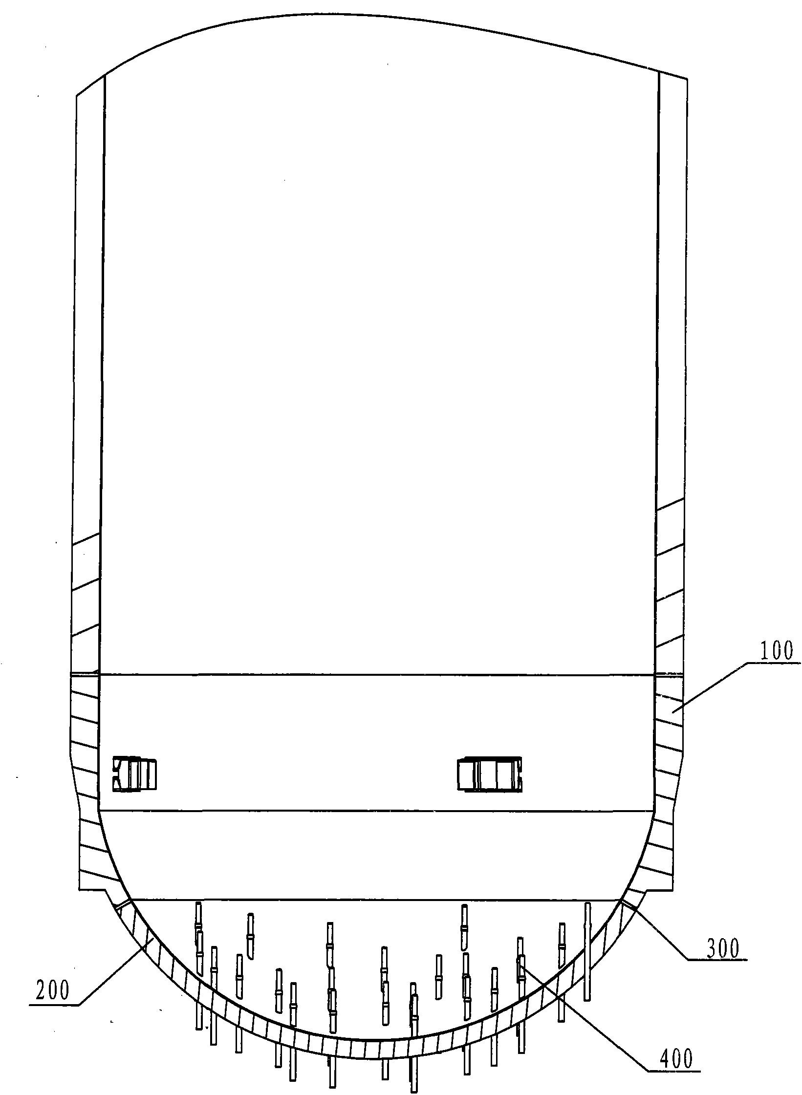
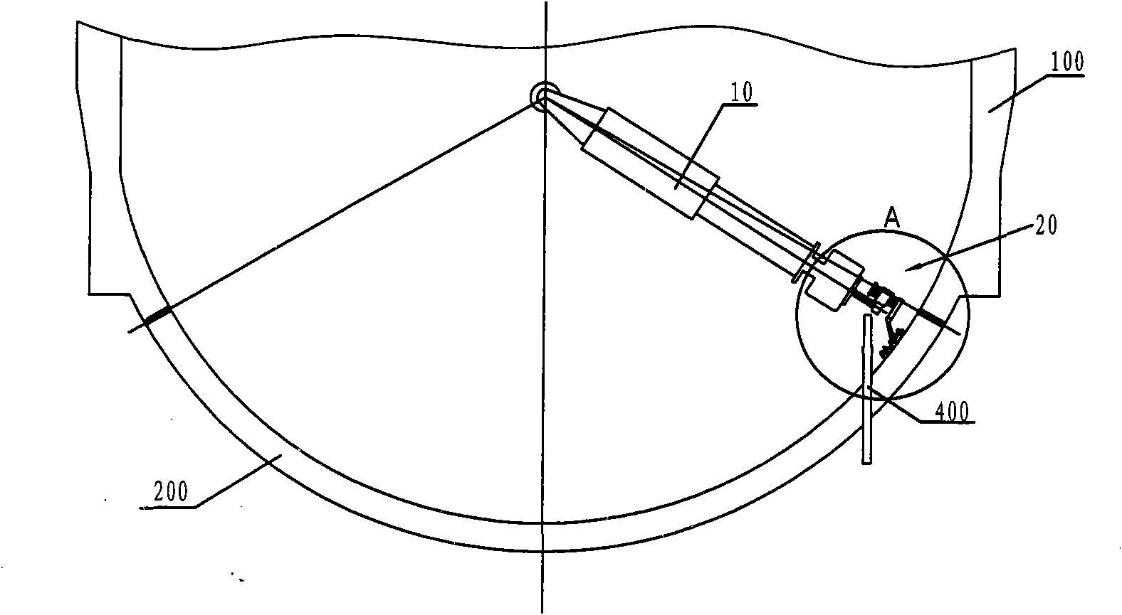
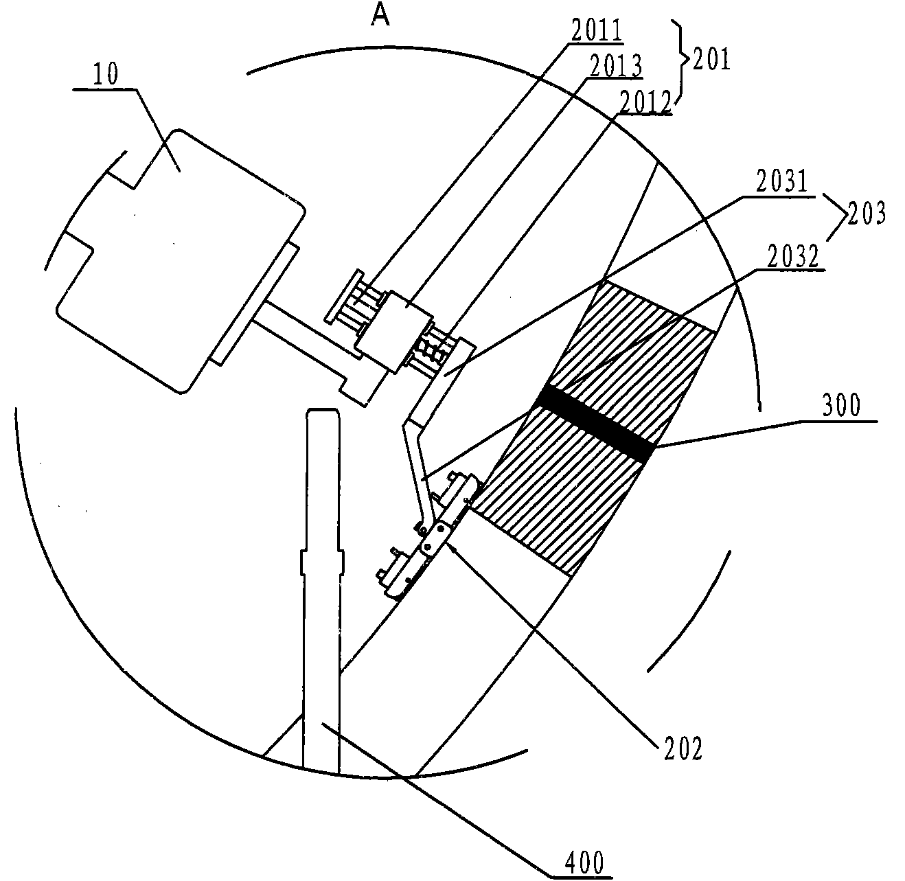
[0022] figure 2 and image 3 It shows the structure and working status of the probe scanning device at the front end of the inspection machine. Since the reactor pressure vessel is a large vessel, the bottom of which is located 20m underwater, and the pressure vessel has relatively large nuclear radiation, and people cannot approach it for operation. Therefore, in order to realize Extend the probe scanning device to the bottom of the container, and set up a large inspection machine (not shown in the figure) outside the container. The core of the inspection machine is to control the position of the probe scanning device and receive the feedback information from the probe. The outside of the inspection machine The mechanical structure and its control system are not the main points of the present invention, which can adopt the structure of the existing in...


PUM


Abstract

The invention relates to a probe scanning device of a reactor pressure vessel inspection machine, comprising an inspection arm and at least one probe assembly connected with the front end of the inspection arm. Each probe assembly comprises a probe mechanism coupled with a spherical surface area to be scanned, a spring cushion test bed used for providing a pressing force for the probe mechanism in the radial direction of the spherical surface and a descending bracket connecting the spring cushion test bed and the probe mechanism; the probe mechanism comprises at least one ultrasonic probe body and a probe fixing frame used for limiting the position of the ultrasonic probe body; the descending bracket comprises a horizontal part and an inclining part which aslant extends to the spherical surface; and the inclining part is pivoted with the probe fixing frame. The probe scanning device prevents the probe mechanism from touching a penetration member and ensures the overall scanning of the area to be scanned, and the ultrasonic probe body can be tightly coupled, which ensures the scanning continuity as well as the reliability and the accuracy of scanning results.

Description

technical field [0001] The invention relates to a nuclear power plant reactor pressure vessel weld seam detection device. Background technique [0002] The lower part of the nuclear reactor pressure vessel is welded by a cylindrical body 100 and a hemispherical lower head 200, such as figure 1 As shown, therefore, there is a weld 300 at the connection between the two under the pressure vessel. According to the relevant inspection specifications of nuclear power plants, the area of ​​50mm on both sides of the weld ( image 3 (shown in the shaded part in the middle) for flaw detection inspection. At the same time, the surfacing layer on the surface also needs to be scanned with the weld as the center line and 250 mm on both sides. In the prior art, there are ultrasonic principles for detection The principle of the inspection machine is to extend the probe into the bottom of the pressure vessel for scanning. Since the area to be scanned is a spherical surface, the installation...

Claims


Application Information

Patent Timeline
Patent Type & Authority Applications(China)
IPC IPC(8): G21C17/01
CPCY02E30/30
Inventor 李明许伟科洪茂成陈怀东肖学柱
Owner CGNPC INSPECTION TECH
Why Eureka
Try Eureka