Motor shell

A motor shell and peripheral technology, which is applied in the direction of the casing/cover/support, electrical components, electromechanical devices, etc., can solve the problem that the installation method of the load-fixed mounting frame cannot be satisfied, and the impact on the manufacturing and use of plastic-sealed motors, installation distance and installation Difficult to adjust the position and other problems, to achieve the effect of convenient and reliable assembly and disassembly, compact structure and low structural cost

Active Publication Date: 2013-02-06
ZHONGSHAN BROAD OCEAN
View PDF0 Cites 2 Cited by
  • Summary
  • Abstract
  • Description
  • Claims
  • Application Information

AI Technical Summary

Problems solved by technology

[0002] At present, plastic-sealed motors are widely used, their insulation and integrity are relatively good, and their quality is stable, but there are still some problems: 1) The bearing chambers of most plastic-sealed motors are generally made of metal materials, and bolts, rivets or embedding are used for assembly. It is fixed on the shell, its positioning accuracy is not high, it requires high assembly technology, and it is noisy during operation, which affects the manufacture and use of plastic-encapsulated motors
2) The casing of the plastic-encapsulated motor is integrally injection-molded with the stator assembly and the circuit board. There is no special stator containment cavity and circuit board containment cavity, and separate assembly or disassembly is not possible, and the casing, stator assembly, and circuit board cannot be recycled independently. 3) It has high requirements for production technology and high manufacturing cost; 4) Its installation method is relatively simple, and the installation distance and installation position are difficult to adjust, which cannot meet the load fixed installation of different customers. The installation method of the rack is poor in versatility

Method used


Image

  • Motor shell
  • Motor shell
  • Motor shell

Examples


Embodiment Construction

[0024] The present invention will be described in further detail below through specific embodiments and in conjunction with the accompanying drawings.

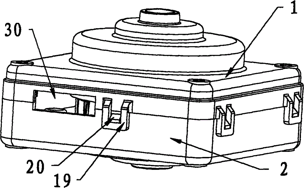
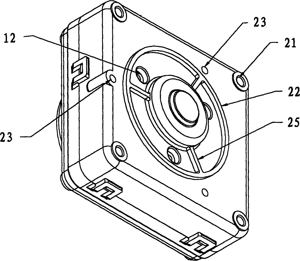
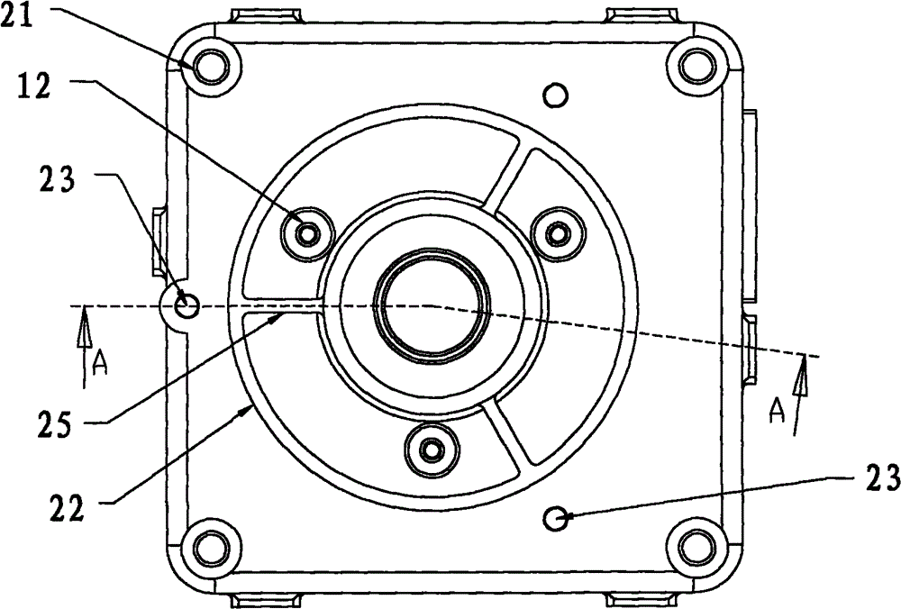
[0025] Such as Figure 1 to Figure 9 As shown, a motor casing includes a front end cover 1 and a rear end cover 2. The front end cover 1 and the rear end cover 2 are installed together to form a plurality of cavities, wherein the top of the front end cover 1 is provided with a first bearing cavity 3, and the first A stator containment cavity 4 is provided below the bearing cavity 3, a circuit board containment cavity 5 is formed below the stator containment cavity 4 and inside the rear end cover 2, and a second bearing cavity is formed below the circuit board containment cavity 5 and the bottom of the rear end cover 2 6.

[0026] Wherein the front end cover 1 and the rear end cover 2 are made of plastics, the area of ​​the circuit board containing cavity 5 is larger than the area of ​​the stator containing cavity 4, and the p...


PUM


Abstract

A motor housing comprises a front end cover (1) and a rear end cover (2). The front end cover (1) and the rear end cover (2) are installed together to form a plurality of cavities. A bearing cavity (3) is provided at the top of the first end cover (1). A stator cavity (4) is provided below the bearing cavity (3). A circuit board cavity (5) is provided below the stator cavity (4) and formed in the rear end cover (2). A bearing cavity (6) is provided below the circuit board cavity (5) and formed at the bottom of the rear end cover (2). The motor housing has a good generality, can be mounted conveniently and reliably, and is suitable for a single-phase brushless motor and a three-phase brushless motor.

Description

Technical field: [0001] The invention relates to a motor housing. Background technique: [0002] At present, plastic-sealed motors are widely used, their insulation and integrity are relatively good, and their quality is stable, but there are still some problems: 1) The bearing chambers of most plastic-sealed motors are generally made of metal materials, and bolts, rivets or embedding are used for assembly. It is fixed on the casing, its positioning accuracy is not high, and it requires high assembly technology, and it is noisy during operation, which affects the manufacturing and use of plastic-encapsulated motors. 2) The casing of the plastic-encapsulated motor is integrally injection-molded with the stator assembly and the circuit board. There is no special stator containment cavity and circuit board containment cavity, and separate assembly or disassembly is not possible, and the casing, stator assembly, and circuit board cannot be recycled independently. 3) It has high...

Claims


Application Information

Patent Timeline
Patent Type & Authority Patents(China)
IPC IPC(8): H02K5/04
CPCH02K5/08H02K11/0073H02K5/15H02K5/1732H02K5/225H02K11/33
Inventor 张旭
Owner ZHONGSHAN BROAD OCEAN
Why Eureka
Try Eureka