LLC (Logical Link Control) series resonance converter and drive method thereof

A series resonance, converter technology, applied in the direction of converting DC power input to DC power output, AC power input converting to DC power output, instruments, etc., can solve problems such as low reliability, improve reliability, and solve reliability problems. lower effect

Active Publication Date: 2010-11-24
ZTE CORP
View PDF5 Cites 39 Cited by
  • Summary
  • Abstract
  • Description
  • Claims
  • Application Information

AI Technical Summary

Problems solved by technology

[0017] The main purpose of the present invention is to provide an LLC series resonant converter and its driving method, to at least solve the above-mentioned problem of low reliability

Method used


Image

  • LLC (Logical Link Control) series resonance converter and drive method thereof
  • LLC (Logical Link Control) series resonance converter and drive method thereof
  • LLC (Logical Link Control) series resonance converter and drive method thereof

Examples


Embodiment Construction

[0029] Hereinafter, the present invention will be described in detail with reference to the drawings and examples. It should be noted that, in the case of no conflict, the embodiments in the present application and the features in the embodiments can be combined with each other.

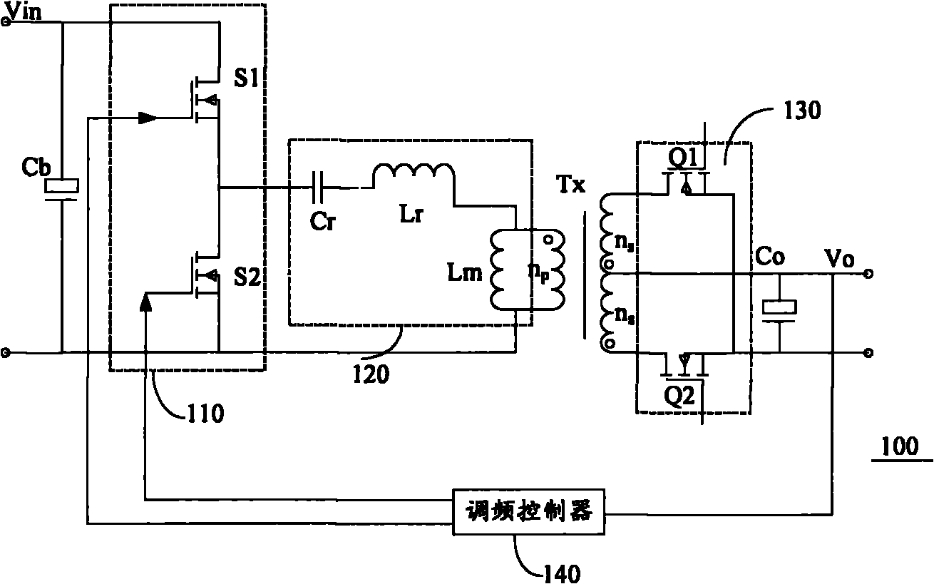
[0030] Figure 6 It is a circuit diagram of the synchronous rectification driving scheme of the LLC series resonant converter 600 proposed by the present invention, including:

[0031] a bridge circuit 110, coupled to the input voltage Vin, composed of two first switches S1, S2;

[0032] a resonant circuit 120, coupled to the bridge circuit 110, driven by the first switches S1, S2;

[0033] a transformer TX, coupled to the resonant circuit 120;

[0034] A rectifier circuit 60, which includes two sub-drive circuits 601, 602, including:

[0035] A second switch Q1, Q2, coupled to both ends of the secondary side of the transformer Tx, for providing the voltage output Vo of the LLC series resonant co...


PUM


Abstract

The invention discloses an LLC (Logical Link Control) series resonance converter and a drive method thereof. The LLC series resonance converter comprises a bridge circuit, a resonance circuit, a transformer and a rectifying circuit, wherein the bridge circuit is coupled to input voltage and comprises at least two first switches; the resonance circuit is coupled to the bridge circuit and driven by the first switches; the transformer is coupled to the resonance circuit; the rectifying circuit comprises two sub drive circuits which respectively comprise a second switch, a shut-off circuit and a pulse width processor; the second switches are coupled to two ends of a secondary side of the transformer and used for providing voltage output of the LLC series resonance converter; the shut-off circuits are used for providing shut-off signals for the second switches, and each shut-off circuit comprises a current transformer which is connected between the secondary side of the transformer and the two second switches in series and used for measuring the current of a source-drain electrode circuit branch, which flows through the second switches, to generate shut-off signals; and the pulse width processors are used for reducing the duty cycle of power switch drive signals of the primary side of the transformer at control ends of the first switches to obtain switch-on signals and provide the signals for the second switches.

Description

technical field [0001] The present invention relates to the communication field, in particular to an LLC series resonant converter and a driving method thereof. Background technique [0002] figure 1 It is a circuit diagram of an LLC series resonant converter composed of synchronous rectification transistors in the prior art, wherein the LLC series resonant converter 100 is mainly composed of a bridge circuit 110 , a resonant circuit 120 and a rectifying circuit 130 . The bridge circuit 110 adopts the control method of the symmetrical half bridge, the upper and lower tubes are complementary conduction, and the duty ratio is 50%; the resonant circuit 120 is composed of a resonant capacitor Cr, a resonant inductance Lr, and an excitation inductance Lm to form a resonant body, and Lr can be used as the leakage inductance of the transformer To make up; rectification circuit 130 is composed of a pair of synchronous rectification transistors Q1 and Q2 connected to the output capa...

Claims


Application Information

Patent Timeline
Patent Type & Authority Applications(China)
IPC IPC(8): H02M3/335H02M7/217
CPCY02B70/1433H02M3/3376Y02B70/1441Y02B70/1491H02M2001/0058H02M1/0058Y02B70/10Y02P80/10
Inventor 范杰王静
Owner ZTE CORP
Why Eureka
Try Eureka