Camera module

A camera module and lens module technology, applied in the field of camera modules with an optical anti-shake function, can solve the problems of increasing the total height of the camera module, increasing the manufacturing cost of the camera module, and unfavorable thinning of the camera module. Achieve the effect of reducing height, saving cost and eliminating image blur

Inactive Publication Date: 2010-11-24
HONG FU JIN PRECISION IND (SHENZHEN) CO LTD +1
View PDF3 Cites 1 Cited by
  • Summary
  • Abstract
  • Description
  • Claims
  • Application Information

AI Technical Summary

Problems solved by technology

Lens anti-shake mainly refers to setting a special anti-shake compensation lens group in the lens module. According to the shake direction and degree of the camera module, the position and angle of the compensation lens group are adjusted accordingly to keep the optical path stable, but adding compensation lens groups will increase The total height of the camera module in the direction of the optical axis is not conducive to the thinning of the camera module
Imaging device anti-shake mainly refers to changing the position or angle of the image sensor to maintain the stability of imaging after sensing the shake of the camera module, but the anti-shake of the imaging device requires a high-precision mechanism to change the position or angle of the image sensor , correspondingly greatly increasing the manufacturing cost of the camera module

Method used


Image

  • Camera module
  • Camera module
  • Camera module

Examples


Embodiment Construction

[0015] The camera module of the technical solution will be further described in detail below in conjunction with the drawings and multiple embodiments.

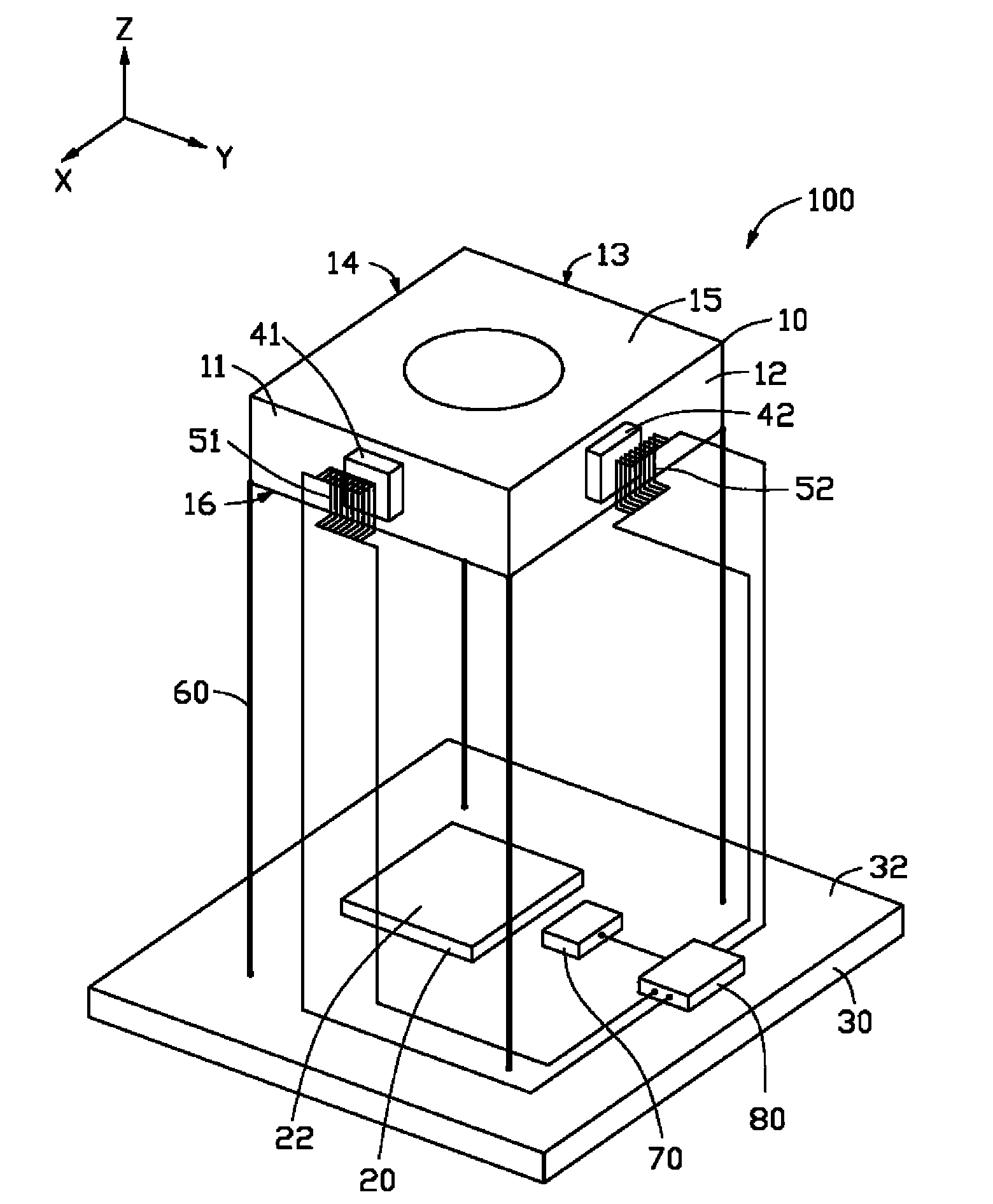
[0016] see figure 1 The optical image stabilization camera module 100 provided in the first embodiment of the technical solution includes a circuit board 30, an image sensor 20, a displacement sensor 70, a processor 80, a lens module 10, a flexible support body 60, a first Magnet 41 , second magnet 42 , first wire 51 , second wire 52 .

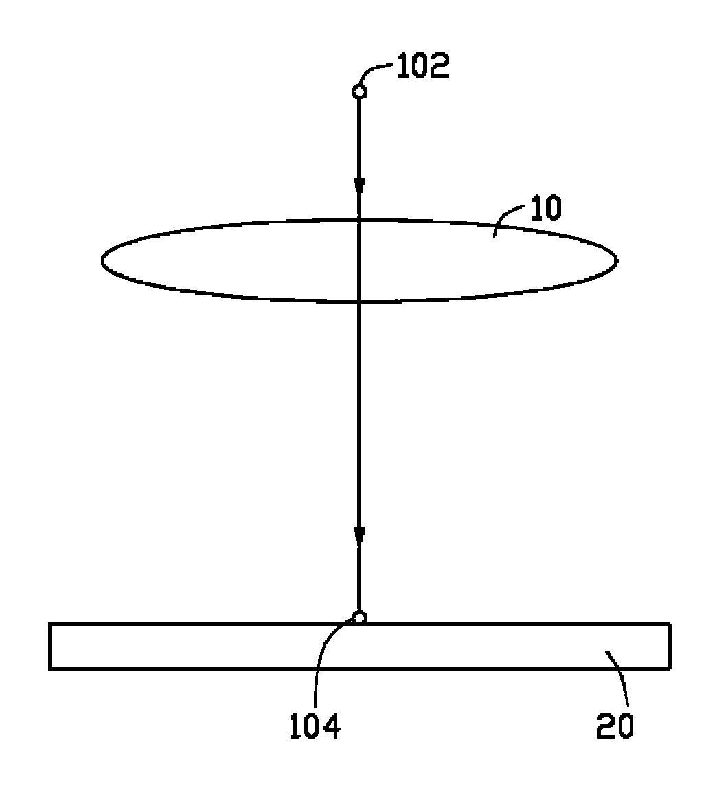
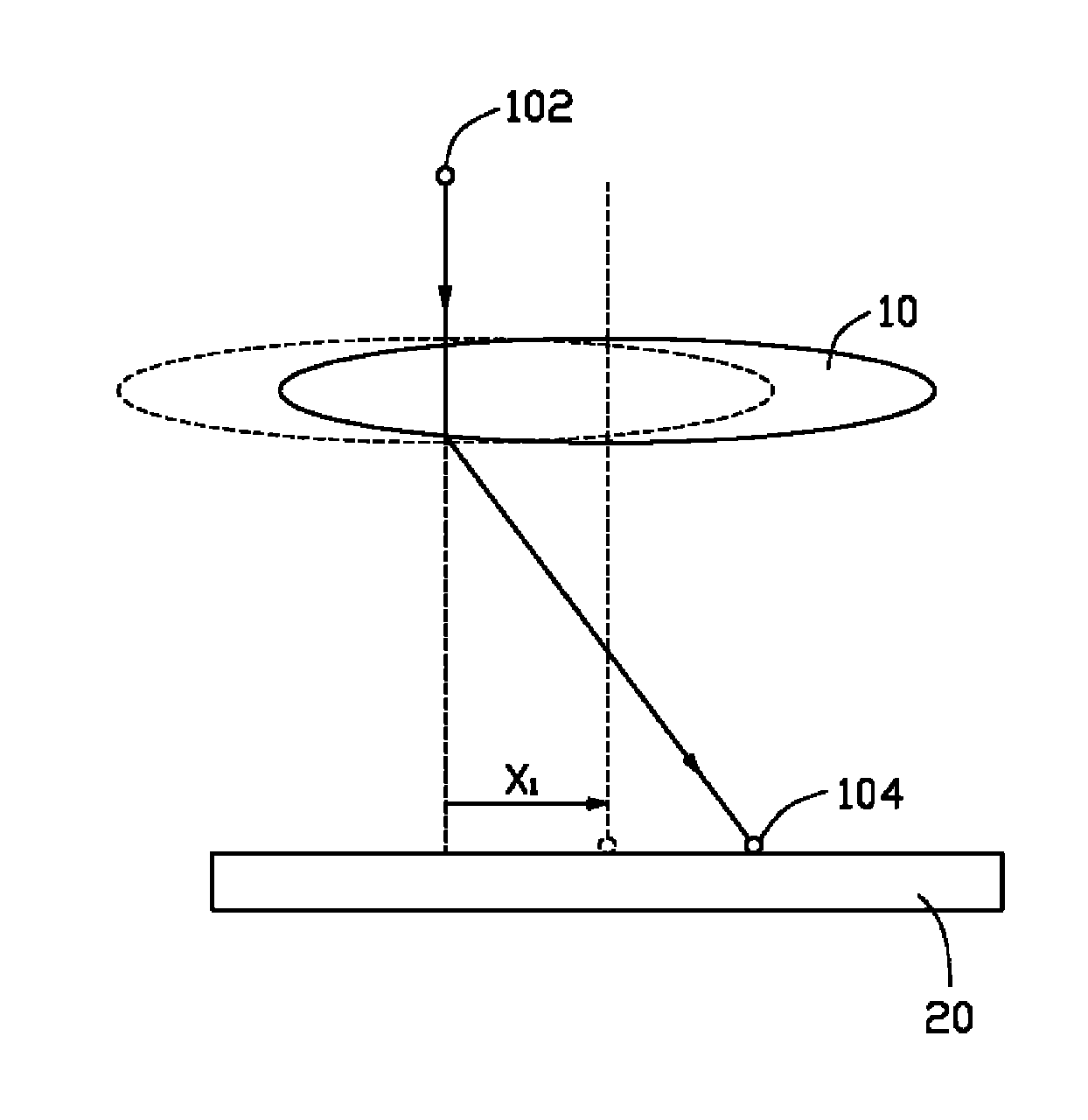
[0017] The circuit board 30 has a surface 32 on which the image sensor 20 , the displacement sensor 70 and the processor 80 are disposed, and the image sensor 20 and the displacement sensor 70 are fixed relative to the circuit board 30 . The lens module 10 is opposite to the image sensor 20 . The image sensor 20 has an image sensing surface 22 perpendicular to the optical axis of the lens module 10 . One end of the flexible supporting body 60 is connected to the surface 32 , and the other ...


PUM


Abstract

The invention provides a camera module, comprising a circuit board, an image sensor, a processor, a displacement sensor and a lens module, wherein the image sensor is arranged on the circuit board; the displacement sensor is used for sensing the offset of the image sensor corresponding to an object to be shot; the lens module comprises a first side face, a second side face, a first wire, a second wire and a plurality of flexible supports; the first side face and the second side face are fixedly provided with a first magnet and a second magnet respectively; the first wire and the second wire are respectively arranged corresponding to the first magnet an the second magnet and are fixed corresponding to the image sensor; the lens module is supported on the circuit board through the flexible supports; and the processor controls the current in the first wire and the second wire to enable the lens module to move due to the reacting force of ampere force applied on the first magnet and the second magnet, therefore the images of the object to be shot are always at the same position of the image sensor.

Description

technical field [0001] The invention relates to the technical field of camera modules, in particular to a camera module with an optical anti-shake function. Background technique [0002] The camera module uses the shutter to control the length of time that the light is projected to the image sensor. For example, when the shutter speed is 1 / 2 second, it means that the time for the image sensor to receive light is 1 / 2 second. If within this 1 / 2 second When the same beam of light moves on the image sensor due to shaking, the image sensor will record the movement track of the light, making the captured photo blurred. In order to compensate for the light offset caused by shaking, camera modules using image stabilization systems to prevent shaking began to appear in the 1990s. For details, please refer to the paper "Optical image stabilization for digital cameras" published by Cardani B. et al. in Control Systems Magazine, IEEE (Volume 26, Issue 2, Page(s): 21-22) in April 2006. ...

Claims


Application Information

Patent Timeline
Patent Type & Authority Applications(China)
IPC IPC(8): H04N5/225H01L27/146G02B7/09
CPCH01L27/14625H04N5/23287H04N5/23248G02B27/646H04N23/68H04N23/687
Inventor 柯朝元
Owner HONG FU JIN PRECISION IND (SHENZHEN) CO LTD
Why Eureka
Try Eureka