
Direct-vision image acquisition system for video signals

An image capture and video technology, applied in the field of direct-view image capture systems, can solve the problems of complex mechanism design, poor practicability, and many components, and achieve the effects of increasing the scope of application, improving the quality of conversation, and reducing costs.

Inactive Publication Date: 2010-11-24
UNIVERSAL MICROELECTRONICS
View PDF1 Cites 0 Cited by
  • Summary
  • Abstract
  • Description
  • Claims
  • Application Information

AI Technical Summary

Problems solved by technology

[0008] 1. Due to the complex design of the mechanism, there are many components in the whole group, the assembly is not easy, and there are disadvantages of high manufacturing cost
[0009] 2. The most important thing is that it is not suitable for video calls between portable devices (such as mobile phones) due to its large overall size, and has the disadvantage of poor practicability

Method used

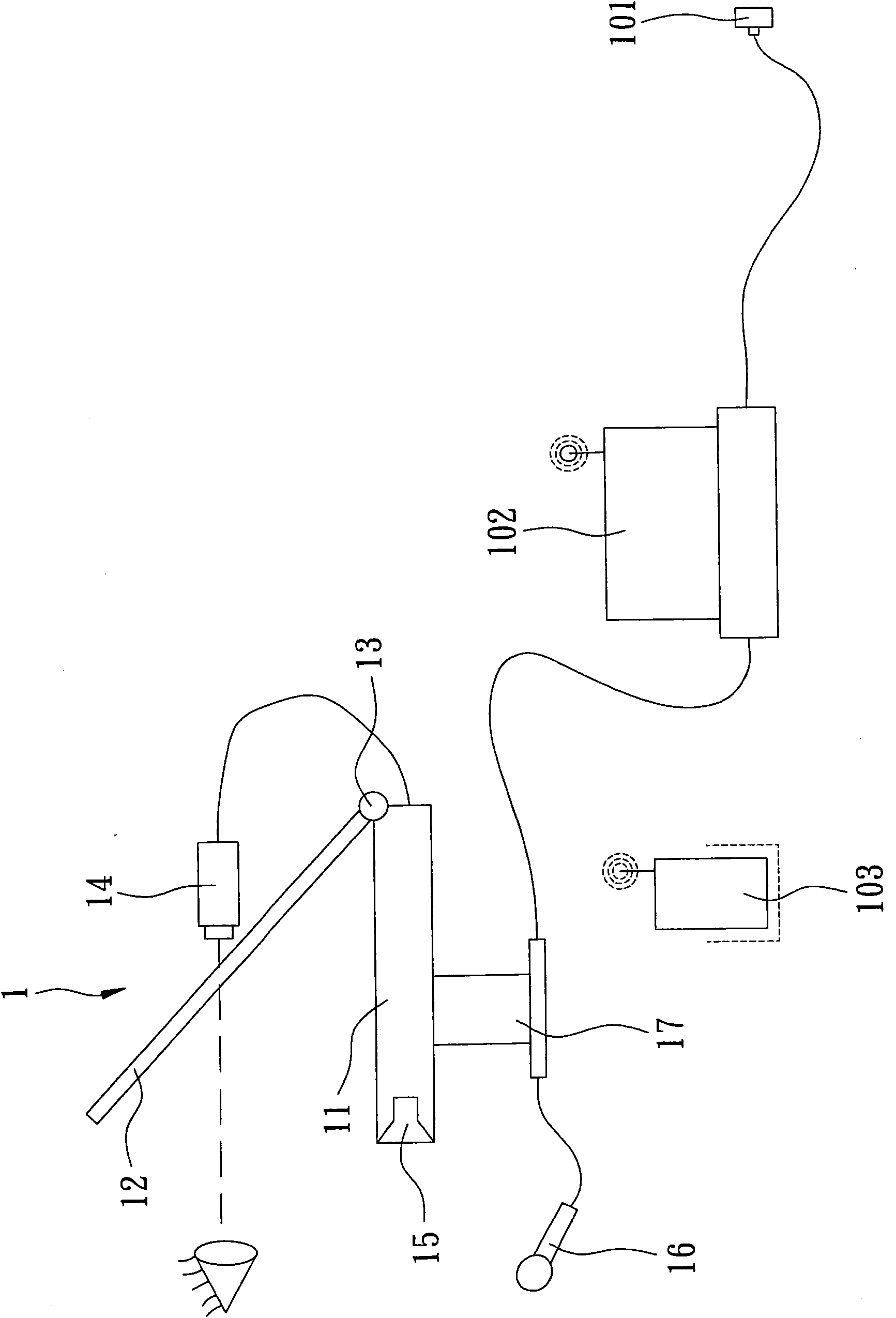

Image

  • Direct-vision image acquisition system for video signals
  • Direct-vision image acquisition system for video signals
  • Direct-vision image acquisition system for video signals

Examples


Embodiment Construction

[0021] Below in conjunction with accompanying drawing and embodiment the present invention is described in detail:

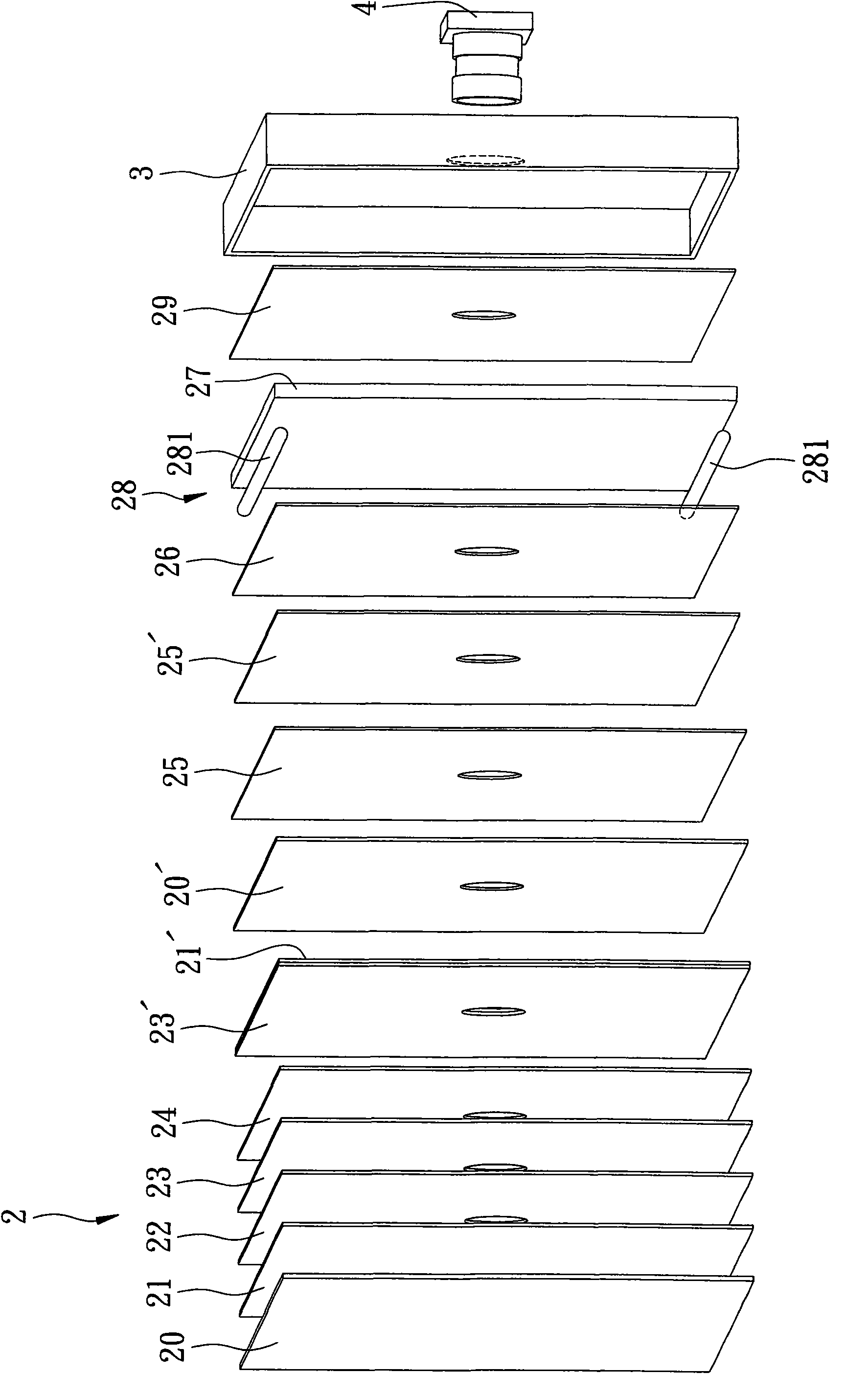
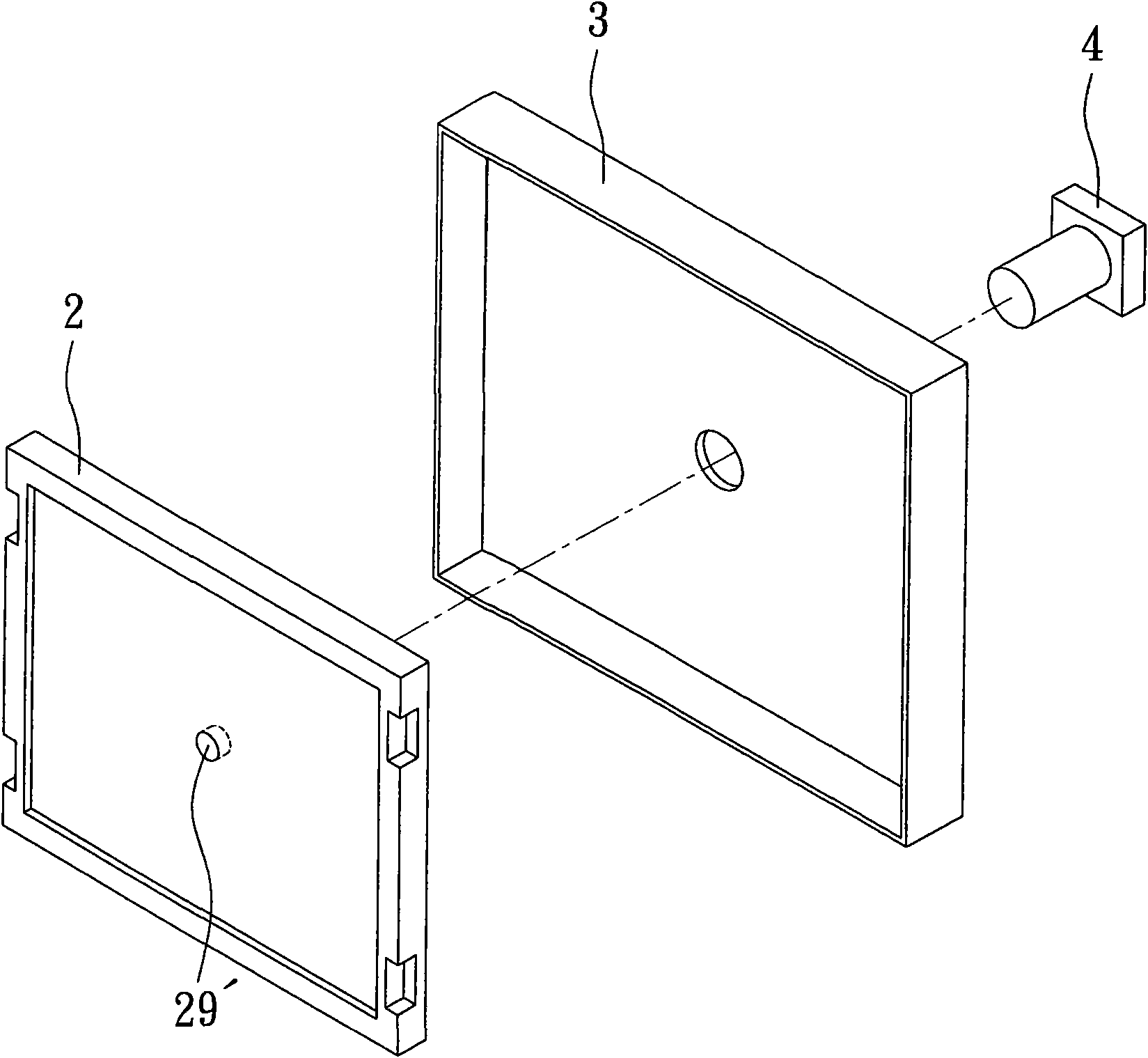
[0022] Such as figure 2 , 3 As shown in , 4, the preferred embodiment of the direct-view image capture system used for video communication in the present invention is suitable for a first user and a second user to carry out video communication, and the system includes: an LCD module 2 , a fixed seat 3 and an image capture unit 4 .

[0023] The LCD module 2 is used to display the image data of the first user, and includes an upper polarizer 20, an upper glass substrate 21, a color filter 22, an upper indium tin oxide layer 23, and a liquid crystal layer 24. A lower indium tin oxide and thin film transistor layer 23', a lower glass substrate 21', a lower polarizer 20', a horizontal diffusion film 25, a vertical diffusion film 25', a diffusion sheet 26, a light guide plate 27, a The backlight 28 adjacent to the light guide plate 27 , a reflective sheet 29 , and...


PUM


Abstract

The invention discloses a direct-vision image acquisition system for video signals, which is used for allowing a first user and a second user to perform video signal communication. The system comprises an LCD module and an image acquisition unit. The LCD module is used for displaying the image data of the first user and comprises a transparent channel which is used for the light rays from the second user to pass through and arranged in an eye contact area. The image acquisition unit is arranged behind the LCD module and used for receiving the image light rays from the second user. By arranging the transparent channel in the eye contact area, in the image, which is transmitted to the counterpart by the image acquisition unit, of a user, the eyes of the user seems to contact the eyes of the counterpart directly, so the video signal talk quality is improved obviously.

Description

technical field [0001] The present invention relates to an image capture system, in particular to a direct-view image capture system for video communication. Background technique [0002] In the past, when people used a video system to make a call, the position of the monitor used to display the other party's image was usually different from the camera used to capture its own image. For example, the camera used by a personal computer was usually set above the display screen, and the camera used by a notebook computer The camera is usually set on the top of the display screen. However, in the actual video call, due to the different positions of the monitor and the camera, in the image of our party sent to the other party, our eyes are usually fixed on the monitor below instead of looking at the camera to talk, so it seems Instead of looking at the other person, it is easy to make the other person feel disrespected, which in turn reduces the quality of the conversation. [0...

Claims


Application Information

Patent Timeline
Patent Type & Authority Applications(China)
IPC IPC(8): H04N7/14G02F1/1333
Inventor 黄崇扬
Owner UNIVERSAL MICROELECTRONICS
Learn More