
Device for injecting a liquid load to be mixed/converted inside a plasma needle or a gaseous flow

A technology of plasma and equipment, applied in the field of liquid injection system, can solve the problems that cannot be satisfied at the same time

Inactive Publication Date: 2012-10-03
COMMISSARIAT A LENERGIE ATOMIQUE ET AUX ENERGIES ALTERNATIVES
View PDF2 Cites 0 Cited by
  • Summary
  • Abstract
  • Description
  • Claims
  • Application Information

AI Technical Summary

Problems solved by technology

[0022] Therefore, none of the existing solutions can simultaneously meet the following requirements:

Method used


Image

  • Device for injecting a liquid load to be mixed/converted inside a plasma needle or a gaseous flow
  • Device for injecting a liquid load to be mixed/converted inside a plasma needle or a gaseous flow
  • Device for injecting a liquid load to be mixed/converted inside a plasma needle or a gaseous flow

Examples


Embodiment Construction

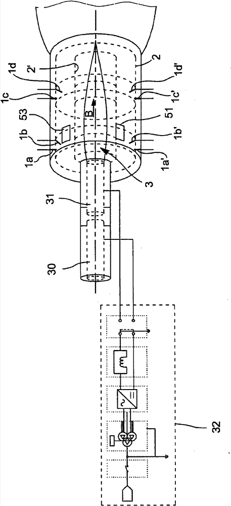
[0076] The following will combine Figure 1A The views shown illustrate one embodiment of the invention.

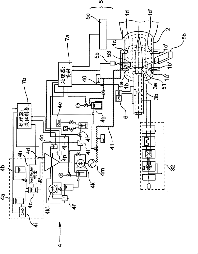
[0077] Figure 1B This device is included with additional peripherals that will be described further.

[0078] exist Figure 1A In the figure, reference numerals 30 and 31 denote electrodes, and discharges are generated between them. At the same time, the passage of the plasmaized gas through these electrodes leads to the formation of a plasma plume 3 .

[0079] The power supply for the electrodes is indicated by reference numeral 32 .

[0080] At the output end of the electrode there is provided a system forming a support 2 for positioning and holding the injector for spraying the liquid to be treated. In a cavity 2' arranged in the support, the plasma plume flows substantially along an axis B, referred to below as the plasma flow axis. In one example, the cavity 2' is substantially cylindrical in shape and the axis B is the cylindrical symmetry axis of the...


PUM


Abstract

The invention relates to a device for injecting a liquid material into a plasma torch, that comprises N (N >= 1) groups of injectors arranged on the periphery of a plasma flow area (3), each group including at least n (n >= 2) injectors (1b, 1b', 1d, 1d', 1f, 1f' ) arranged on either side of the plasma flow axis, in order to inject said liquid material into said plasma in a direction (10, 10') atleast partially opposite to the plasma flow direction.

Description

technical field [0001] The present invention relates to the technical field of liquid injection systems for injecting liquid towards the plume (flare) of a plasma torch. Background technique [0002] For the liquid to be converted in the flare, examples that may be mentioned are bio-oils, or slurries from wastewater treatment plants, or "mortars" or particles from pulverized solids, which are mixed with the liquid for injection into the plasma Inside the plume of the body torch. [0003] The main problem encountered in the process of gasifying liquid materials by plasma, especially for bio-oils, is how to better use a plasma torch to achieve the conversion. [0004] For bio-oils, this is achieved by flash pyrolysis, a thermochemical process (at a temperature of T≈500°C) in which deoxygenation (dioxygene stoichiometry) is not carried out The biomass (biomaterial) is rapidly heated under the hood. Under the action of heat, this biomass decomposes and leads to the formation ...

Claims


Application Information

Patent Timeline
Patent Type & Authority Patents(China)
IPC IPC(8): H05H1/42
CPCF23G2209/10F23G5/085H05H1/42F23G2209/12F23G2204/201
Inventor 梅莉尔·布罗捷大卫·格纳杜帕特里克·格拉蒙迪
Owner COMMISSARIAT A LENERGIE ATOMIQUE ET AUX ENERGIES ALTERNATIVES
Learn More