Thread-free floating type supporting bar

A support rod, floating technology, applied in the field of support rods, can solve the problems of easy fracture compensation, poor strength, inconvenient maintenance of support rods, etc., to achieve overall strength improvement, simple and convenient disassembly and installation, and eliminate harmful shocks and vibrations Effect

Inactive Publication Date: 2010-12-01
关海龙 +1
View PDF0 Cites 5 Cited by
  • Summary
  • Abstract
  • Description
  • Claims
  • Application Information

AI Technical Summary

Problems solved by technology

[0015] In order to solve the problems of inconvenient maintenance, poor strength, easy breakage and poor compensation of existing support rods, the present invention further provides a threadless floating support rod

Method used


Image

  • Thread-free floating type supporting bar
  • Thread-free floating type supporting bar
  • Thread-free floating type supporting bar

Examples


specific Embodiment approach 1

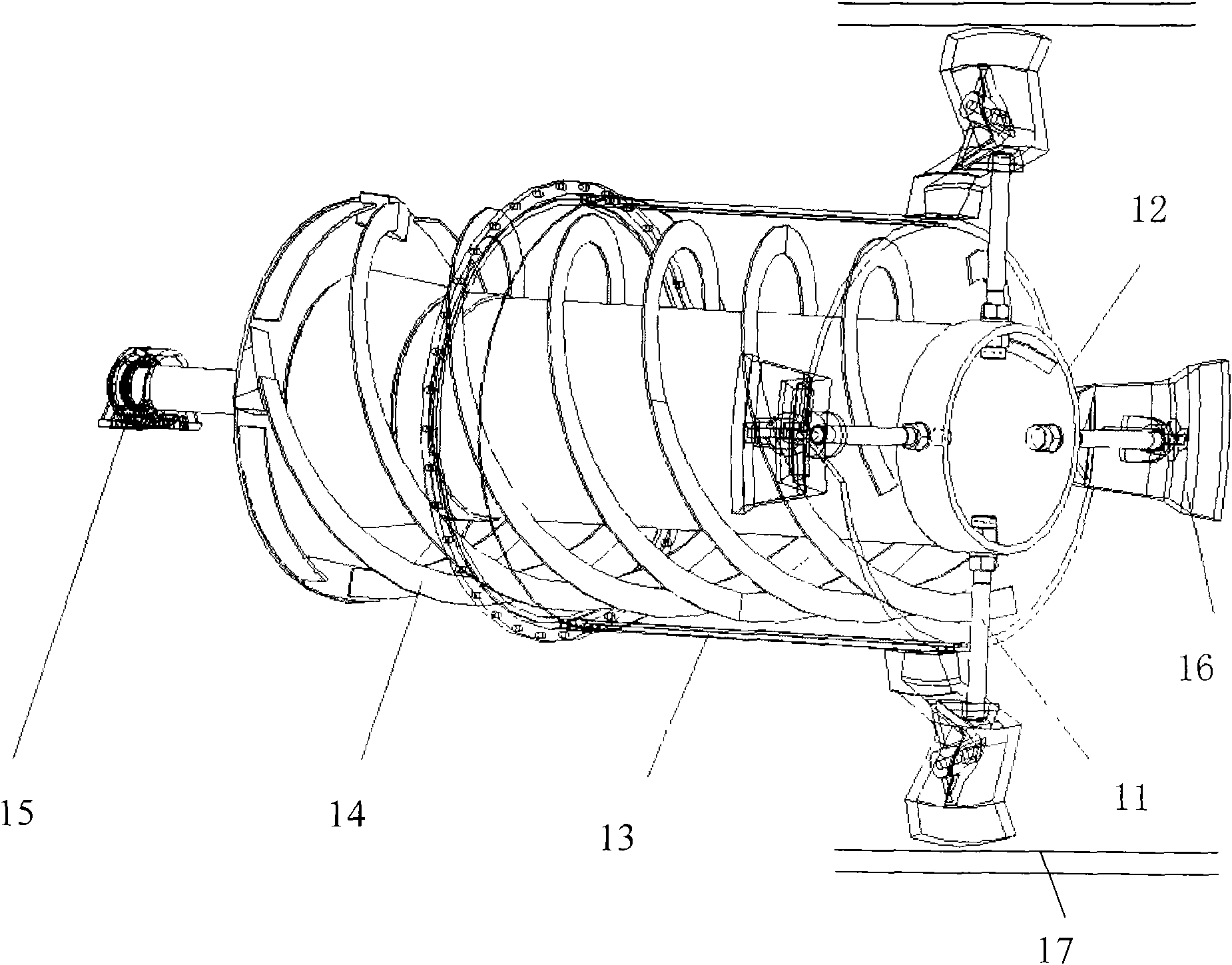
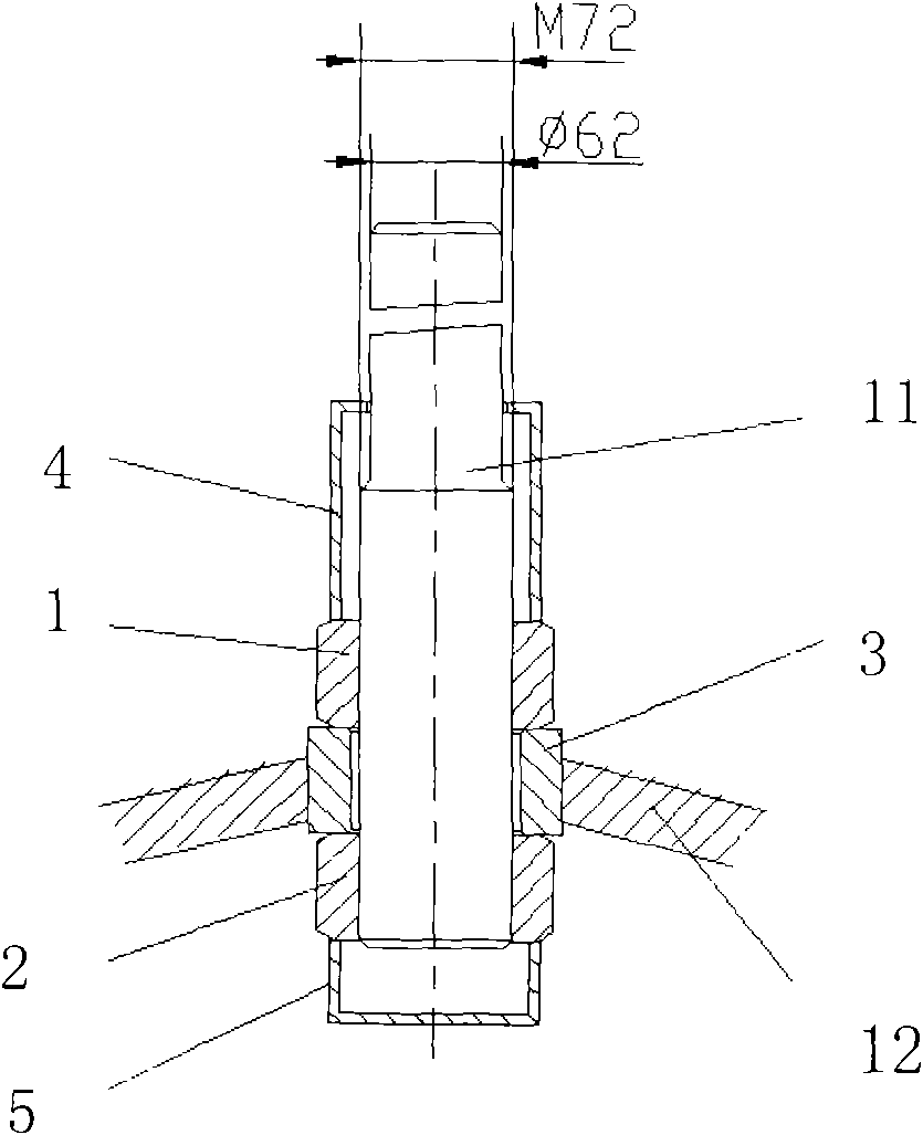
[0025] Specific implementation mode one: as Figure 6 As shown, the threadless floating support rod in this embodiment is composed of a support rod main body 21, a support rod main body sleeve 22, a disc spring 23, a gland 24 and at least two connecting pieces 25. The support rod main body The shaft sleeve 22 passes through the hole 12-1 provided on the side wall of the central tube 12 and is fixedly connected with the central tube 12. One end of the support rod main body 21 is inserted into one end of the support rod main body shaft sleeve 22 located outside the central tube 12. The spring 23 is installed in the other end of the main body sleeve 22 of the support rod inside the central tube 12. One end surface of the main body of the support rod 21 is in contact with the disc spring 23. It is detachably connected with the gland 24 through a connecting piece 25 . The other end of the support rod main body 21 is connected to the inner wall of the coal pulverizer barrel through...

specific Embodiment approach 2

[0026] Specific implementation mode two: as Figure 6 As shown, the connector 25 in this embodiment is a bolt. So set, easy to disassemble. Threads are canceled on the support rod, disc springs can compensate for the gap between the support rod and the cylinder liner, and the gland 24 is connected by bolts (connector 25), which is detachable. Other components and connections are the same as those in the first embodiment.

specific Embodiment approach 3

[0027] Specific implementation mode three: as Figure 6 As shown, the main body 21 of the support rod in this embodiment is made of high-quality carbon steel 45# steel or low-alloy steel Q345. Originally, the material of the support rod was medium alloy steel 34CrNi3Mo. Due to the structural change, this embodiment not only improves the strength but also greatly reduces the material cost. Other compositions and connections are the same as those in Embodiment 1 or 2.


PUM


Abstract

The invention relates to a thread-free floating type supporting bar, in particular to a construction member used for fixing a spiral propeller onto a coal mill barrel in a BBD steel ball coal mill. The invention solves the problems that the existing supporting bar is inconvenient for maintenance, has poor strength and is easy to break and compensatory is poor. The shaft sleeve of the supporting bar main body penetrates a hole opened on the side wall of a central tube and is fixedly connected with the central tube, one end of the supporting bar main body is inserted and arranged in one end of the supporting bar main body shaft sleeve outside the central tube, a disk spring is arranged in the other end of the supporting bar main body shaft sleeve inside the central tube, one end of the supporting bar main body is connected with the disk spring by contact, and the other end of the supporting bar main body shaft sleeve is connected with a gland by a connecting piece in a dismountable way. The invention has simple and feasible mounting, can be dismounted and can be repeatedly used; clearance compensation changes the stress state of the supporting bar, thus improving the strength of the supporting bar; and different axiality compensation between the spiral propeller and the barrel optimizes the working condition of the spiral propeller.

Description

technical field [0001] The invention relates to a support rod, in particular to a component used in a BBD steel ball coal mill for fixing a screw propeller on a coal mill barrel. Background technique [0002] 1. The role of the support rod [0003] The screw propeller is an important part of conveying raw coal in the BBD steel ball coal mill (see figure 1 ), the screw propeller is fixed on the cylinder of the coal mill by four support rods. When the cylinder rotates, the torque is transmitted to the propeller by the support rod, so that the propeller rotates synchronously with the cylinder. During this process, the screw blades on the screw propeller push the raw coal into the barrel. It can be seen that the support rod plays an important role in the BBD steel ball coal mill. [0004] 2. The structure of the existing support rod [0005] In order to ensure that the coaxiality between the centerline of the propeller and the centerline of the cylinder meets the requirement...

Claims


Application Information

Patent Timeline
Patent Type & Authority Applications(China)
IPC IPC(8): B02C17/18
Inventor 关海龙陈岩
Owner 关海龙
Why Eureka
Try Eureka