Plate and stripe rolling mill and plate and stripe edge shape control method

A strip and rolling mill technology, which is applied in the field of strip rolling mill and strip edge shape control, can solve the problems that the strip edge shape cannot be adjusted to meet the requirements, and the contact length cannot be changed.

Active Publication Date: 2014-01-22
ZHEJIANG HUADA NEW MATERIAL
View PDF6 Cites 4 Cited by
  • Summary
  • Abstract
  • Description
  • Claims
  • Application Information

AI Technical Summary

Problems solved by technology

[0003] The invention provides a strip mill and a strip edge shape control method capable of changing the contact length of the middle roll surface, which solves the problem that the existing strip edge shape cannot be adjusted to qualifying questions

Method used


Image

  • Plate and stripe rolling mill and plate and stripe edge shape control method
  • Plate and stripe rolling mill and plate and stripe edge shape control method
  • Plate and stripe rolling mill and plate and stripe edge shape control method

Examples


Embodiment 1

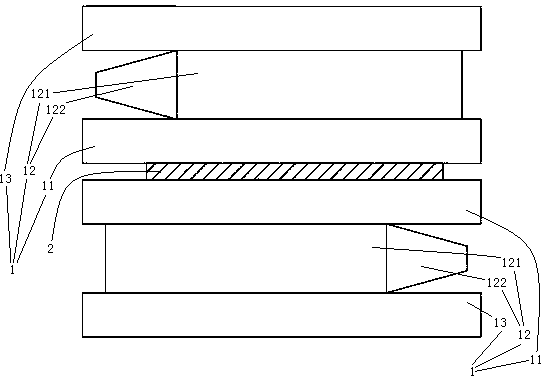
[0024] Embodiment one, see figure 1 , a strip rolling mill, comprising two sets of rolls 1 oppositely arranged along the up and down directions. The roll set 1 includes a work roll 11 , an intermediate roll 12 and a back-up roll 13 arranged in sequence.

[0025] The intermediate roll 12 comprises a cylindrical section 121 and a conical section 122 . The conical section 122 is located at one axial end of the cylindrical section 121 . The conical section 122 and the cylindrical section 121 are connected together in the form of an integral structure. Of course, it is also possible to connect them together by welding. The tapered section 122 on the middle roller in two groups of roll groups 1, the tapered section on one middle roller is positioned at the left end of middle roller, and the tapered section on the other middle roller is positioned at the right end of middle roller.

[0026] When in use, the strip 2 advances from between the two sets of rolls 1 in a direction perp...

Embodiment 2

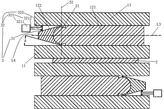
[0028] Embodiment two, see figure 2, the difference from the first embodiment is that the conical section 122 is hinged on the end surface of the cylindrical section 121 by means of spherical fit. A conical section inclination adjustment mechanism 3 is provided between the conical section 122 and the supporting roller 13 . The conical section inclination adjustment mechanism 3 includes a push block 31 and a driving mechanism 32 . One end of the push block 31 abuts against the supporting roller 13 , and the other end abuts against the tapered section 122 . Both the axis L3 of the cylindrical section and the axis L4 of the tapered section pass through the center of the spherical surface S1 where the mating surfaces of the cylindrical section and the tapered section are located. The center of the spherical surface S1 where the mating surfaces of the cylindrical section and the tapered section are located is located on the plane S2 where the bottom end of the tapered section is...

Embodiment 3

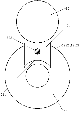
[0031] Embodiment three, see Figure 4 , The difference with the second embodiment is: the limit groove on the push block 31 and the tapered section 122 are in surface contact. The push block 31 is supported by the support roller 13 via the driving mechanism 32 .

[0032] see Figure 5 , the driving mechanism 32 includes a hydraulic cylinder 323 and a push rod 324 . The hydraulic cylinder 323 includes a hydraulic cylinder body 3231 and a hydraulic cylinder piston 3232 located in the hydraulic cylinder body. One end of the push rod 324 is fixedly connected to the hydraulic cylinder piston 3232 , and the other end is fixedly connected to the push block 31 . The hydraulic cylinder body 3231 abuts against the support roller 13 . The center line L1 of the cylinder block of the hydraulic cylinder is an arc line. The centerline of the circle where the centerline L1 of the cylinder block of the hydraulic cylinder is located extends along the traveling direction of the strip (that...


PUM


Abstract

The invention relates to a rolling mill and a rolling method. The plate and stripe rolling mille comprises two roller sets which are oppositely arranged. Each roller set comprises a work roller, a middle roller and a supporting roller which are sequentially arranged, wherein the middle roller comprises a column-shaped section and a conical section connected with one end of the column-shaped section. The directions of the conical sections of the middle rollers of the two roller sets are opposite. The plate and stripe rolling mill and a plate and stripe edge shape control method can change the contact lengths of roller faces of the middle rollers and solve the problem that in the prior art, the contact lengths of the roller faces of the middle rollers cannot be changed to prevent plate and stripe edge shapes from being adjusted to meet requirements.

Description

technical field [0001] The invention relates to a rolling mill and a rolling method, in particular to a strip rolling mill and a strip edge shape control method. Background technique [0002] A large number of 6-roll mills or multi-roll mills are used in metal cold-rolled strip mills, that is, intermediate rolls are used in addition to work rolls and backup rolls. In Chinese patent No. 2012203566440, the publication date is March 13, 2013, and the patent document titled "rolling mill" promptly discloses a six-high rolling mill. However, in strip rolling, when the roll exerts a large rolling force on the cable tie (strip steel), the deformation force of the strip steel causes elastic bending of the work rolls that are in direct contact with the strip steel, causing the edge of the strip steel to drop sharply. , resulting in edge wavy formation and edge thinning. For this reason, the 6-roll mill or multi-roll mill controls the force on the edge of the strip through t...

Claims


Application Information

Patent Timeline
Patent Type & Authority Applications(China)
IPC IPC(8): B21B37/40B21B37/30B21B27/02B21B13/04
Inventor 刘毅
Owner ZHEJIANG HUADA NEW MATERIAL
Why Eureka
Try Eureka