Main shaft assembly of continuous copper extruding machine

A technology of extruder and main shaft, applied in the field of main shaft assembly of copper continuous extruder, can solve the problems of large temperature stress, uneven temperature distribution of extrusion wheel, falling off (dropping iron, etc.)

Inactive Publication Date: 2018-01-12
大连康丰科技有限公司
View PDF5 Cites 1 Cited by
  • Summary
  • Abstract
  • Description
  • Claims
  • Application Information

AI Technical Summary

Problems solved by technology

[0002] The working principle of the copper continuous extrusion machine is: the extrusion wheel is driven by the motor to rotate, the copper rod billet enters the wheel groove of the extrusion wheel, and due to the friction of the groove wall of the wheel groove, the metal rod billet is drawn to the extrusion wheel and the cavity. In the formed arc-shaped extrusion cavity, under the action of high pressure and high temperature generated by friction, the copper rod billet is extruded through the die mouth. The main products include copper flat wire, copper round wire, copper busbar, copper bar, copper strip blank and Special-shaped copper materials, etc., because the extrusion wheel is subjected to the extrusion force during work, and due to the friction between the extrusion wheel and the billet, the vicinity of the extrusion wheel groove and the outer surface of the extrusion wheel are still in a high temperature state. The extrusion temperature is controlled, and the inside of the extrusion wheel is cooled by water. The stress on the extrusion wheel is ver

Method used


Image

  • Main shaft assembly of continuous copper extruding machine
  • Main shaft assembly of continuous copper extruding machine
  • Main shaft assembly of continuous copper extruding machine

Examples


Embodiment Construction

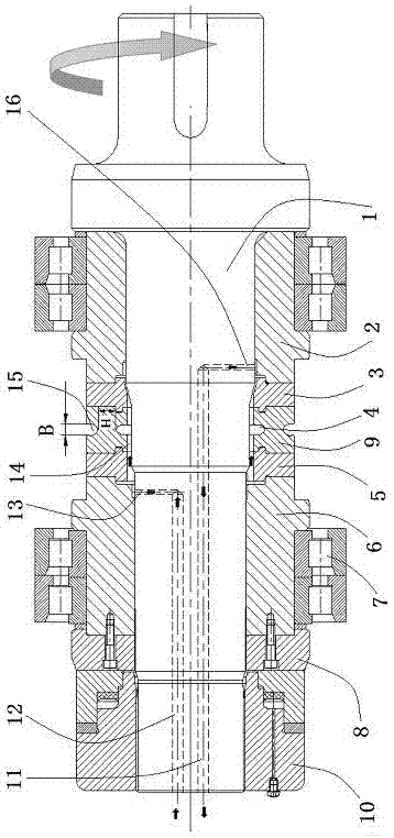
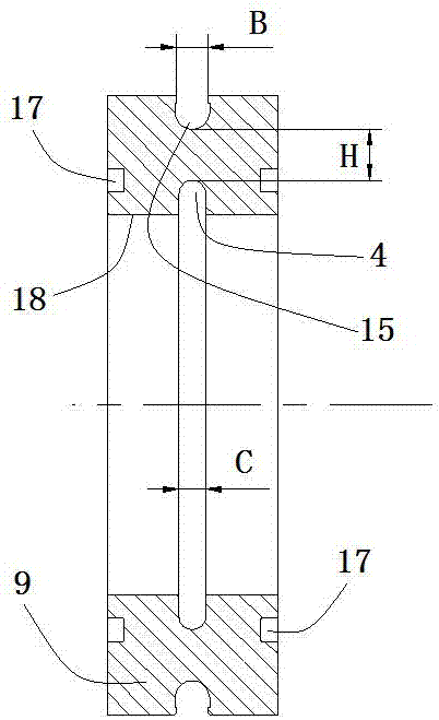
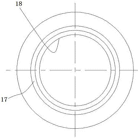
[0015] Such as Figure 1 to Figure 3 As shown, the main shaft assembly of the copper continuous extrusion machine includes the mandrel 1, the inner shaft sleeve 2, the inner wheel 3, the outer wheel 5, the outer shaft sleeve 6, the bearing 7, the pressure sleeve 8, the extrusion wheel 9 and the hydraulic nut 10. The inner shaft sleeve 2 and the outer shaft sleeve 6 are respectively installed on the outside of the mandrel 1, the bearing 7 is installed outside the inner shaft sleeve 2 and the outer shaft sleeve 6, the inner wheel 3 is installed inside the inner shaft sleeve 2, and the outer wheel 5 Installed on the inside of the outer sleeve 6, the pressure sleeve 8 is installed on the outside of the outer sleeve 6, the squeeze wheel 9 is installed between the inner wheel 3 and the outer wheel 5, and the hydraulic nut 10 is installed on the outside of the pressure sleeve 8 and threaded with the mandrel 1 Auxiliary connection, the mandrel 1 is provided with an axial water inlet 1...


PUM


Abstract

The invention discloses a main shaft assembly of a continuous copper extruding machine. The main shaft assembly comprises a core shaft, an inner shaft sleeve, an inner side wheel, an outer side wheel,bearings, a pressing sleeve, an extruding wheel and a hydraulic nut, wherein the inner shaft sleeve and the outer shaft sleeve are mounted on the outer side of the core shaft; the bearings are mounted at the outer parts of the inner shaft sleeve and the outer shaft sleeve separately; an axial water inlet, an axial water outlet, a radial water inlet and a radial water outlet are formed in the coreshaft; the axial water inlet communicates with the radial water inlet; the axial water outlet communicates with the radial water outlet; an annular cooling groove is formed in the inner surface of the extruding wheel; and the part between the inner surface of the extruding wheel and the outer surface of the core shaft forms an annular gap which serves as a cooling water channel. According to themain shaft assembly of the continuous copper extruding machine, the cooling water channel of the extruding wheel of the main shaft assembly is changed, so that when the groove temperature of the extruding wheel is controlled and the softening of the extruding wheel in the high temperature area in the groove is reduced, the temperature distribution and stress condition of the extruding wheel are changed, the stress value of the extruding wheel at the dangerous breakdown point is reduced, the service life of the extruding wheel is prolonged, and the equipment operation cost is reduced.

Description

technical field [0001] The invention relates to a copper continuous extrusion machine mainly used for continuous extrusion and continuous coating of copper and copper alloy metals, and also used for cable manufacturing in the wire and cable industry, especially relates to a spindle assembly of a copper continuous extrusion machine . Background technique [0002] The working principle of the copper continuous extrusion machine is: the extrusion wheel is driven by the motor to rotate, the copper rod billet enters the wheel groove of the extrusion wheel, and due to the friction of the groove wall of the wheel groove, the metal rod billet is drawn to the extrusion wheel and the cavity. In the formed arc-shaped extrusion cavity, under the action of high pressure and high temperature generated by friction, the copper rod billet is extruded through the die mouth. The main products include copper flat wire, copper round wire, copper busbar, copper bar, copper strip blank and Specia...

Claims


Application Information

Patent Timeline
IPC IPC(8): B21C23/21B21C29/00
Inventor 刘元文闫志勇
Owner 大连康丰科技有限公司
Why Eureka
Try Eureka