
Switching mechanism of pneumatic nailing machine

A switch mechanism and trigger technology, applied in nailing tools, manufacturing tools, etc., can solve the problems of pneumatic nailing machine batter and other problems, and achieve the effect of reducing processing cost, using safety, and improving the qualification rate of one-time installation.

Inactive Publication Date: 2010-12-01
浙江沃力森工具有限公司
View PDF9 Cites 4 Cited by
  • Summary
  • Abstract
  • Description
  • Claims
  • Application Information

AI Technical Summary

Problems solved by technology

[0010] Without increasing the production cost, in order to solve the problem of continuous strike phenomenon when the pneumatic nailing machine is used, the invention provides a switch mechanism of the pneumatic nailing machine

Method used


Image

  • Switching mechanism of pneumatic nailing machine
  • Switching mechanism of pneumatic nailing machine
  • Switching mechanism of pneumatic nailing machine

Examples


Embodiment Construction

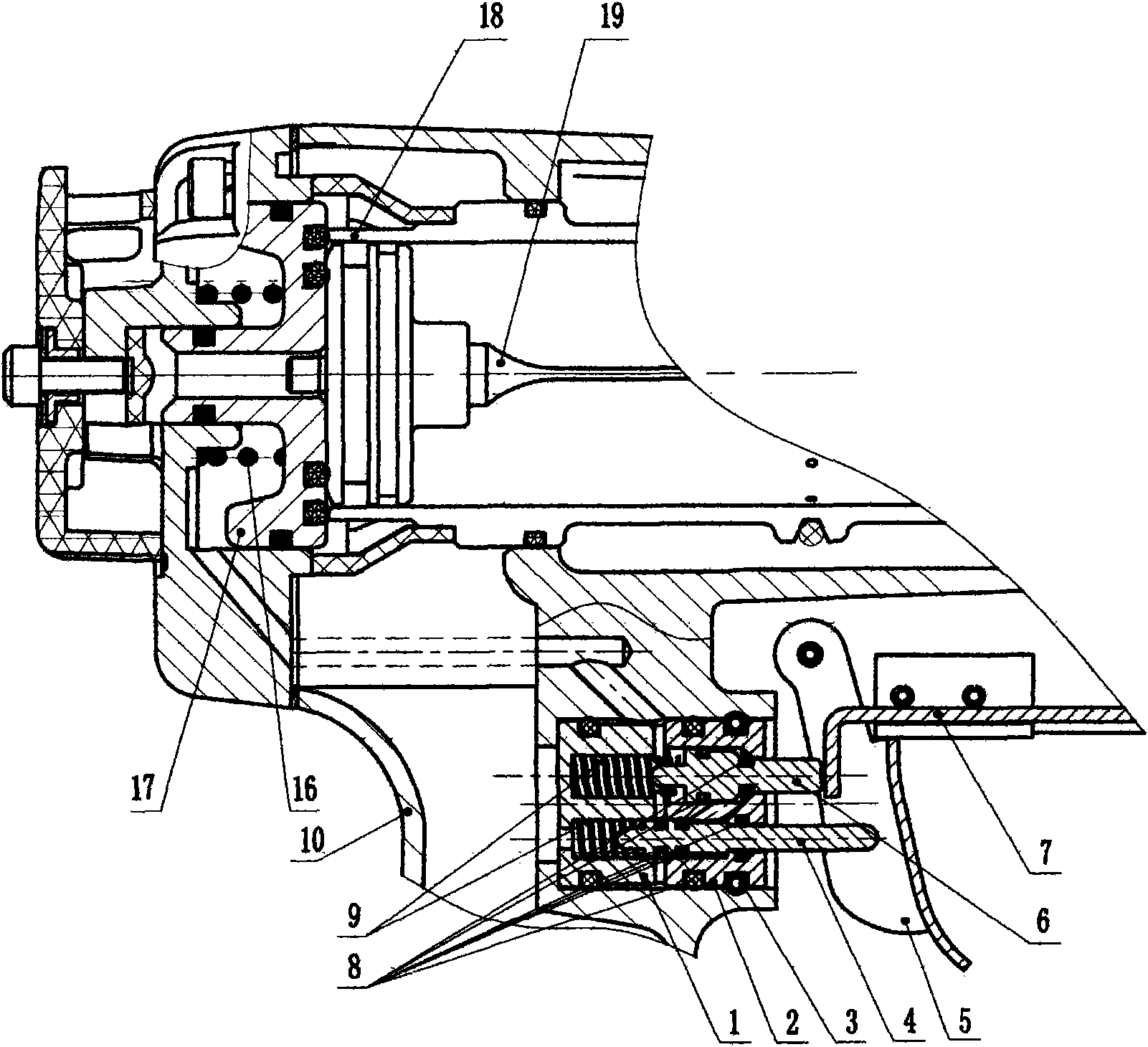
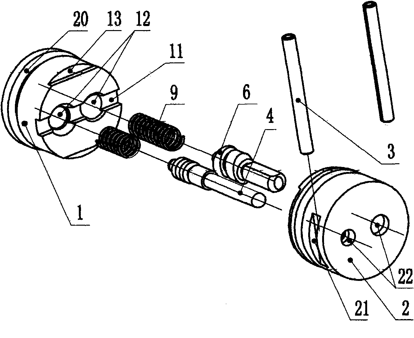
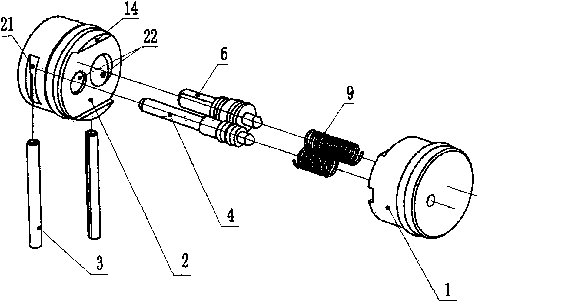
[0025] Such as figure 1 , figure 2 , image 3 , Figure 4 As shown, the present invention is mainly composed of an upper air guide sleeve 1, a lower air guide sleeve 2, an elastic cylindrical pin 3, a trigger 5, a safety frame assembly 7, an "O" ring 8, and a valve stem compression spring 9; Roots are the lower valve stem 4 and the upper valve stem 6 respectively. The upper air guide sleeve 1 is provided with an outer ring groove 20 on its periphery, and an "O" ring 8 is installed on the outer ring groove for sealing with the housing 10. The middle groove 11 opened in the middle of the front side plays the role of air flow direction. Two holes 12 are also arranged in the middle to play a guiding and sealing role, and two sunken steps 13 cooperate with the lower air guide sleeve 2 . The lower air guide sleeve 2 plays the role of sealing and fixing the upper air guide sleeve 1. Two outer grooves 21, two bosses 14 and two holes 22 are arranged on both sides of the lower air ...


PUM


Abstract

The invention discloses a switching mechanism of a pneumatic nailing machine, which comprises a safety bracket assembly, an upper air guide sleeve, a lower air guide sleeve, an elastic cylindrical pin, two valve rods, a trigger, an O-shaped ring and two valve rod pressure springs, wherein the two valve rods are distinguished as an upper valve rod and a lower valve rod; the safety bracket assembly is connected with the upper valve rod and is used for controlling the horizontal movement of the upper valve rod; an outer annular groove is arranged at the periphery of the upper air guide sleeve, the middle of the upper air guide sleeve is provided with two holes, the middle of the front side is provided with a middle groove, and both sides of the middle groove are respectively provided with a step; the O-shaped ring is arranged in the outer annular groove; the lower air guide sleeve is provided with two outer grooves, two bosses, two holes and an inclined hole, and the two valve rod pressure springs support the upper valve rod and the lower valve rod; and the two holes are positioned in the middle of the lower air guide sleeve, and the inclined hole is penetrated between the two holes. The pneumatic nailing machine avoids the double hit phenomenon in the nailing process, increases the one-time installation qualification rate, improves the quality of the pneumatic nailing machine and enables the use to be safer and more reliable.

Description

technical field [0001] The invention relates to a switch mechanism of a pneumatic nailing machine, in particular to a switch mechanism with a safety function controlled by a safety component. Background technique [0002] Pneumatic nailing machines with insurance and switch mechanisms currently on the market are nothing more than the following two structures: [0003] 1. Add a safety buckle under the trigger. When the safety buckle is screwed to the bottom of the trigger, if the trigger is not in place, nailing cannot be performed; when nailing, the gas in the balance valve is also discharged through the switch rod. [0004] 2. Add a safety sheet on the trigger. Only through the action of the safety sheet can the safety mechanism perform the nailing work under the condition of pressing the trigger. When nailing, the gas in the balance valve is also discharged through the switch rod. [0005] The above two insurance institutions have their own shortcomings: [0006] The fir...

Claims


Application Information

Patent Timeline
Patent Type & Authority Applications(China)
IPC IPC(8): B25C1/04
Inventor 吕文理杨章和佘海文陈进友
Owner 浙江沃力森工具有限公司
Learn More