
Real-time on-site drilling full parameter optimization method

An optimization method and a full-parameter technology, applied to drilling equipment, automatic drilling control systems, earthwork drilling and production, etc., can solve problems such as rheological model deviation, hydraulic prediction is difficult to implement, and optimization work is difficult to be accurate, etc., to achieve results Reliable, easy to implement, and the effect of maximizing drilling efficiency

Inactive Publication Date: 2010-12-01
HALLIBURTON ENERGY SERVICES INC
View PDF7 Cites 22 Cited by
  • Summary
  • Abstract
  • Description
  • Claims
  • Application Information

AI Technical Summary

Problems solved by technology

[0006] In addition, the performance of the mud changes with temperature and pressure, and is affected by pollutants such as drilling cuttings. Moreover, the rheological model of the mud has deviations, and the structure of the drilling tool and the geometry of the wellbore have complex hydraulic calculations for the drilling mud. Therefore, hydraulic forecasting is difficult to implement, and optimization work is difficult to be accurate

Method used


Image

  • Real-time on-site drilling full parameter optimization method
  • Real-time on-site drilling full parameter optimization method
  • Real-time on-site drilling full parameter optimization method

Examples


example 1

[0170] Example 1—Optimized calculation of jet impact force of drill bit nozzle

[0171] The pump displacement and pressure measurement data of an on-site hydraulic optimization are shown in Table 1, and the total flow area of ​​the old drill bit nozzle, mud density, rated pump pressure and rated output water power of the mud pump are known at the time of pressure measurement. And it is known that the new drill bit is designed with three nozzles, and the optimization limit condition is the rated pump pressure.

[0172] Table 1. Known data for drill bit hydraulic optimization

[0173] Pump displacement 1, l / s

[0174] The constant C=1.10 is selected, u=1.658 and k=0.079 can be obtained according to formula 10, and then the optimized pump displacement, the total flow area of ​​the drill nozzle and the optimized impact force of the drill jet can be obtained as follows through formulas 16, 17 and 18 ,As shown in table 2.

[0175] Table 2. Data calculated by drill bit hy...

example 2

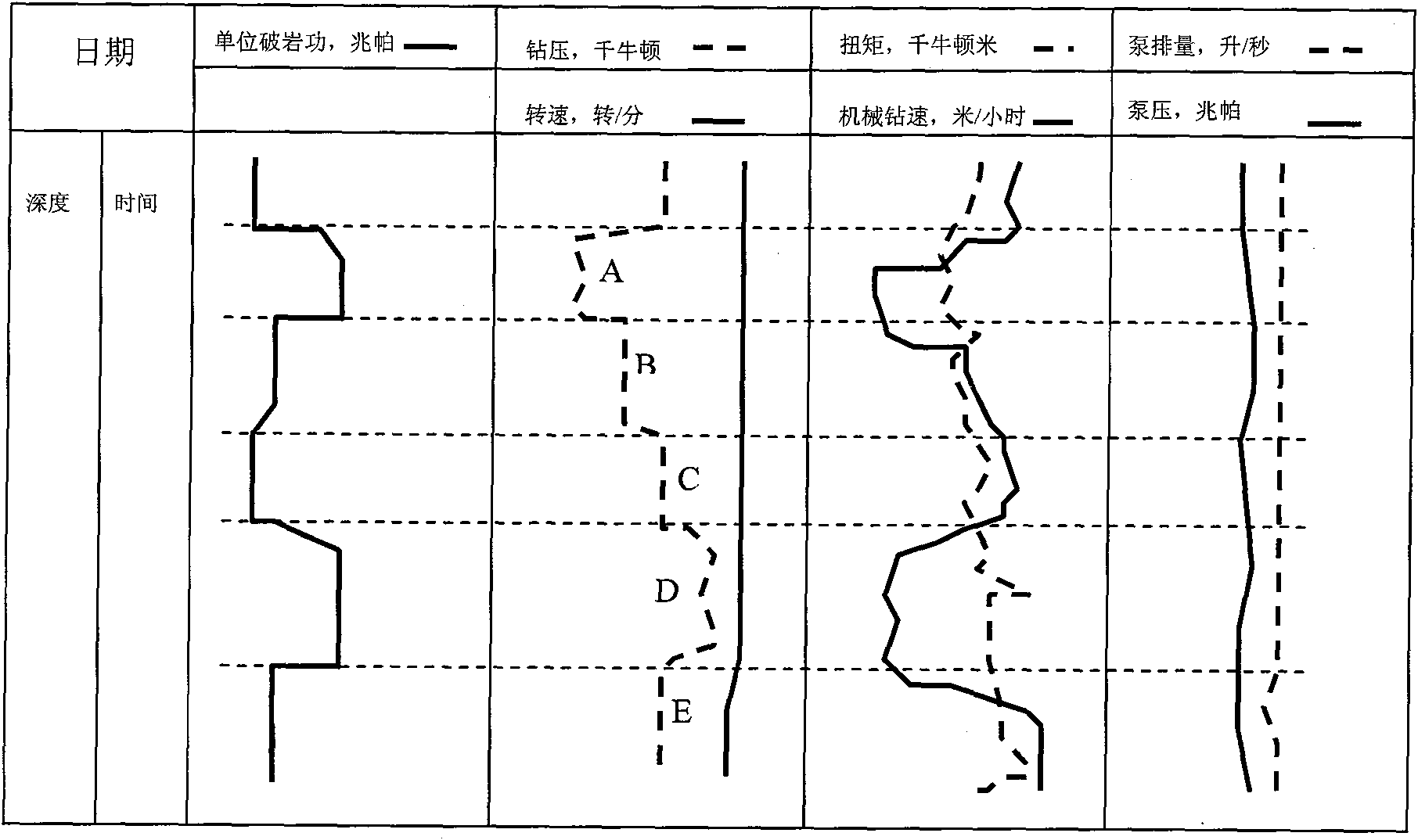
[0178] Example 2—Optimization of WOB

[0179] attached figure 1 Shown is an example of weight-on-bit optimization. It is an optimized operation that only changes the weight on bit while controlling the hydraulic power (pump displacement, pump pressure) and rotational speed of the constant drill bit. It can be seen that when the WOB changes from small to large, it goes through the A-B-C-D time period. In this time period, it can be seen that the unit rock breaking work in the lower WOB section A is larger. With the increase of the WOB, from B to B The unit rock-breaking work of section C is small, and when the WOB increases to D section, the unit rock-breaking work increases to a larger value, indicating that in the WOB section B and C, the cutting efficiency of the drill bit is very high, while In sections A and D, the cutting efficiency of the drill bit is very low due to too small and too large bit pressure. Although the ROP lags behind, it can be seen that the ROP is low...


PUM


Abstract

The invention provides a real-time on-site drilling full parameter optimization method which mainly comprises three parts of hydraulic optimization, bit pressure optimization and rotating speed optimization. The method comprises the following steps of: determining an optimal hydraulic parameter according to a relation between a pump output and a pump pressure, which is obtained by field measurement, and selecting the size of a bit nozzle; and under this premise, determining an optimal bit pressure and a rotating speed relative to a current drilling stratum through observing variation of unit rock fracture work of a bit in real time when the bit pressure and the rotating speed are adjusted. Drilling site operators can accordingly optimize the drilling hydraulic power, the bit pressure and the rotating speed in real time and on the site, thereby maximizing drilling efficiency and drilling mechanical penetration speed and prolonging service lift of the bit or improving drilling footage of a single bit.

Description

technical field [0001] The invention relates to an oil and natural gas drilling engineering, in particular to an optimization method for drilling process parameters of the drilling engineering. Background technique [0002] Oil and gas development is generally exploited by drilling, and drilling is completed through the rock breaking process of the drill bit. The main way of modern drilling is rotary drilling. Rotary drilling is a drilling method that breaks rock by rotating the drill bit. The rock breaking efficiency of the drill bit directly affects the drilling speed. Generally, rotary drilling is to pressurize the drill bit, so that the drill bit can cut into the rock surface, and provide shear energy by rotating the drill bit and break the rock by moving the cutting part. The drill string used for drilling is hollow. During the drilling process, the mud pump pressurizes the drilling mud through the surface manifold and then pumps it from the center of the drill string ...

Claims


Application Information

Patent Timeline
IPC IPC(8): E21B44/00E21B21/08E21B47/00
Inventor 王洪
Owner HALLIBURTON ENERGY SERVICES INC
Learn More