Dual-cylinder dual-return stroke staged combustion device

A staged combustion and double-return technology, which is applied in the direction of combustion methods, combustion equipment, and solid fuel combustion, can solve the problems of poor ignition performance of the burner, inability to rotate the combustion flame, and inability to fully burn, etc., to solve ignition difficulties, The effect of sufficient heat release and height reduction

Inactive Publication Date: 2015-05-27
广东迪奥技术有限公司
View PDF8 Cites 0 Cited by
  • Summary
  • Abstract
  • Description
  • Claims
  • Application Information

AI Technical Summary

Problems solved by technology

Most of the combustion devices of existing boilers or hot blast stoves use direct-flow single-return pulverized coal burners, and their characteristics are as follows: 1. There is only a single combustion return stroke, and the combustion stroke is short, which cannot fully burn, resulting in a certain amount of heat loss. It can fully burn inferior coal powder or cinder powder; 2. The combustion flame cannot rotate, the jet expansion angle is small, the entrainment capacity is small, the burner's ignition performance is poor, and the furnace fullness is poor; 3. Due to the small return flow area at the outlet of the DC burner , the ignition conditions are very poor, and it is very difficult to burn anthracite with low volatile content, and it is even more difficult for low-quality coal powder; 4. Due to insufficient combustion, the emission has a relatively large pollution to the environment and cannot meet environmental protection requirements

Method used


Image

  • Dual-cylinder dual-return stroke staged combustion device
  • Dual-cylinder dual-return stroke staged combustion device
  • Dual-cylinder dual-return stroke staged combustion device

Examples


Embodiment Construction

[0021] The present invention will be described in detail below in conjunction with the accompanying drawings and specific embodiments.

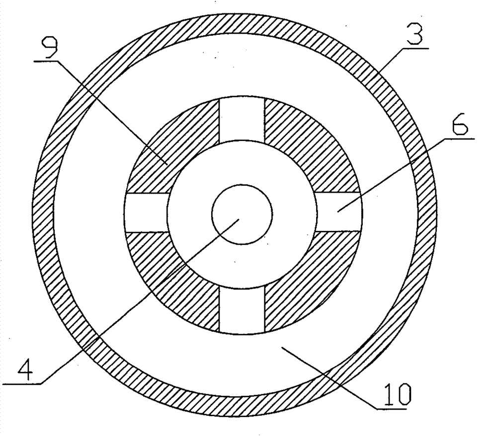
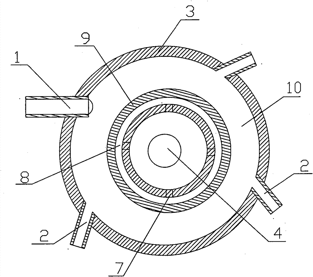
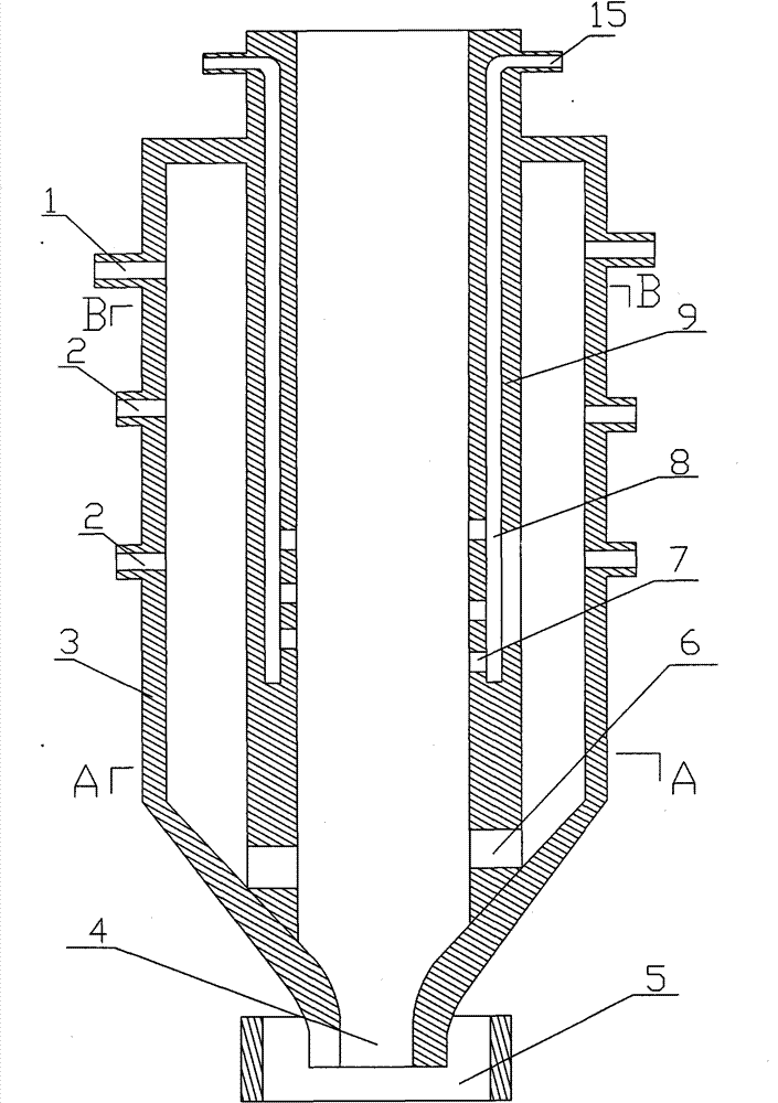
[0022] A double-barrel double-return staged combustion device, such as Figure 1~3 As shown, comprising the outer cyclone combustion tube 3, at least one combustion lance 1 that injects fuel into the outer cyclone combustion tube at a high speed is provided on the upper side of the outer layer cyclone combustion tube, and the side wall of the outer layer cyclone combustion tube is provided with at least one One primary tangential air supply port 2. The outer cyclone combustion tube 3 is provided with an inner cyclone combustion tube 9, and the side wall of the inner cyclone combustion tube 9 forms a closed combustion interlayer 10 with the side wall of the outer cyclone combustion tube 3. In the combustion interlayer At least one flame through hole 6 is arranged on the side wall of the inner cyclone combustion cylinder at the bottom of 10, a...


PUM


Abstract

The invention relates to a dual-cylinder dual-return stroke staged combustion device which comprises an outer-layer cyclone combustion cylinder, a combustion spray gun which sprays fuel into the outer-layer cyclone combustion cylinder at high speed is arranged on the upper side surface of the outer-layer cyclone combustion cylinder, a one-time tangential air supply outlet is arranged on the side wall of the outer-layer cyclone combustion cylinder, an inner-layer cyclone combustion cylinder body is arranged in the outer-layer cyclone combustion cylinder, the side wall of the inner-layer cyclone combustion cylinder body and the side wall of the outer-layer cyclone combustion cylinder form a closed combustion interlayer, a flame through hole is arranged on the side wall of the inner-layer cyclone combustion cylinder body at the bottom part of the combustion interlayer, a slag removing port is arranged at the bottom part of the inner-layer cyclone combustion cylinder, and a residual slag tank is arranged at the slag removing port for containing falling ash slag after burnout. The dual-cylinder dual-return stroke staged combustion device has the following benefits: (1) the dual-layer structure can lead flame after fuel combustion to be turned upwards, thereby prolonging the retention time, realizing full combustion, leading the residual slag after the combustion to fall into the residual slag tank through the slag removing port, reducing the emissions of harmful substances and effectively reducing the environmental pollution.

Description

Technical field: [0001] The invention relates to a combustion device, in particular to a double-cylinder double-return staged combustion device capable of burning inferior fuels such as inferior coal powder or cinder powder. Background technique: [0002] my country is a big country of energy consumption. In the total energy consumption of the country, coal occupies a large proportion, reaching more than 75%. All countries in the world are adjusting their energy structure to save the use of existing energy to the greatest extent and reduce the increasing environmental pollution. The situation of energy conservation and emission reduction is quite severe for our country, and the country is also trying every means to solve the above problems. In addition, with the continuous rise of fuel oil prices, coal prices are also rising sharply, especially high-quality bituminous coal, the price is ridiculously high, which greatly increases the operating costs of enterprises. Therefor...

Claims


Application Information

Patent Timeline
Patent Type & Authority Patents(China)
IPC IPC(8): F23B10/00F23L9/06
Inventor 刘效洲张红斌王红胜
Owner 广东迪奥技术有限公司
Why Eureka
Try Eureka