
Measuring method of package thermal strain of radio frequency micro electromechanical system device

A microelectromechanical system and device packaging technology, which is applied in the field of measuring thermal strain of radio frequency microelectromechanical system device packaging, can solve the problem that the measurement accuracy is affected by the structural shape and scale, the measurement accuracy is affected by the grating scale and accuracy, and the measurement accuracy and low sensitivity, to achieve online measurement, reduce measurement costs, and simplify the measurement process.

Inactive Publication Date: 2010-12-01
SOUTHEAST UNIV
View PDF2 Cites 4 Cited by
  • Summary
  • Abstract
  • Description
  • Claims
  • Application Information

AI Technical Summary

Problems solved by technology

The current measurement methods for thermal strain of MEMS device packaging mainly include: (1) Optical microscopic measurement method, the basic principle of which is to measure the deformation of a specific test structure such as a strain gauge under thermal stress to determine the thermal strain of the package. The disadvantage is that the measurement The accuracy is affected by the shape and scale of the structure, and the measurement error is relatively large; (2) Optical interferometry, such as moiré interference fringe method, the basic principle is to combine the specimen grid that is made on the surface of the structure and deforms with the structure with the sample grid that does not deform with the structure The reference gratings are in contact with each other and overlap, thus forming moiré due to interference. The moiré can be analyzed to measure the thermal strain of the package. The disadvantage is that the measurement accuracy is affected by the scale and precision of the grating, and the measurement accuracy and sensitivity are not high.
And the above optical methods all need special measuring instruments and measuring methods

Method used


Image

  • Measuring method of package thermal strain of radio frequency micro electromechanical system device
  • Measuring method of package thermal strain of radio frequency micro electromechanical system device
  • Measuring method of package thermal strain of radio frequency micro electromechanical system device

Examples


Embodiment

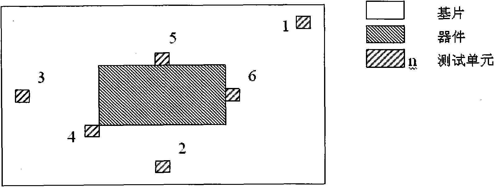
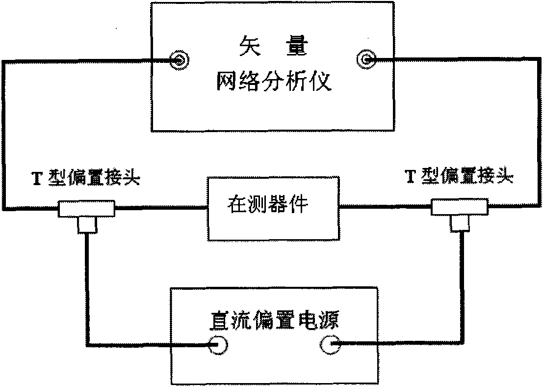
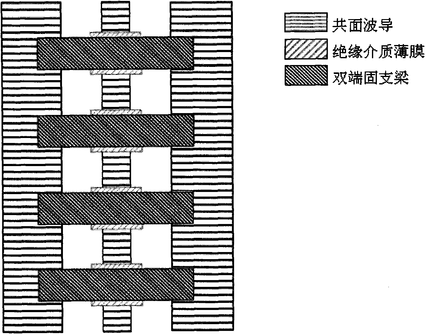
[0018] Example: as figure 1 , image 3 and Figure 4 As shown, a method for measuring thermal strain of a radio frequency MEMS device package includes the following steps:

[0019] (1) Simultaneous production of test units with RF MEMS devices:

[0020] Coplanar waveguide is formed by sputtering a metal film on a low-loss substrate and etching it; depositing an insulating dielectric film and etching only the part covering the overlapping area of ​​the coplanar waveguide signal line and the double-ended clamped beam; spin coating sacrificial layer, the anchor area window of the double-ended fixed beam is etched on the sacrificial layer; the metal film is sputtered and etched to form the beam structure, and then thickened by electroplating; finally, the sacrificial layer is removed by wet etching to release the beam structure;

[0021] (2) If figure 2 As shown, a microwave network measurement system consisting of a vector network analyzer, a DC bias power supply, and a T-t...


PUM


Abstract

The invention discloses a measuring method of package thermal strain of radio frequency micro electromechanical system device (RF MEMS), wherein the specified position of a substrate and the RF MEMS device are provided synchronously with a group or a plurality of groups of test units which are load transmission lines consisting of high impedance coplanar waveguide and a plurality of dual-end fixing beam spanned on it periodically; the relation between the mechanical characteristics and the electrical characteristics of the load transmission line is used for determining the RF MEMS device package thermal strain. The invention measures the RF MEMS device package thermal strain by using microwave measuring means; the manufacture of the test unit is compatible to the manufacturing technique of the RF MEMS device, which can be carried out synchronously.

Description

technical field [0001] The invention relates to a method for measuring the thermal strain of a radio frequency micro-electromechanical system device package. Background technique [0002] RF Micro-Electro-Mechanical System, referred to as: RF MEMS. The current measurement methods of thermal strain of MEMS device packaging mainly include: (1) Optical microscopic measurement method. The accuracy is affected by the shape and scale of the structure, and the measurement error is large; (2) Optical interferometry, such as the moiré interference fringe method, the basic principle is to make the grid on the surface of the structure and deform with the structure. The reference gratings are in contact and overlap with each other, thus forming moiré due to interference. The moiré can be analyzed to measure the thermal strain of the package. The disadvantage is that the measurement accuracy is affected by the size and accuracy of the grating, and the measurement accuracy and sensitivit...

Claims


Application Information

Patent Timeline
Patent Type & Authority Applications(China)
IPC IPC(8): G01B7/16
Inventor 赵成黄庆安宋竟
Owner SOUTHEAST UNIV
Learn More