Bidirectional clamping mechanism

A technology of two-way clamping and power mechanism, which is applied in the direction of clamping, metal processing machinery parts, support, etc., can solve the problems of machining accuracy deviation, inconsistent centerline deviation, etc., and achieve the effect of improving machining accuracy

Inactive Publication Date: 2010-12-08
邝锦富
View PDF7 Cites 48 Cited by
  • Summary
  • Abstract
  • Description
  • Claims
  • Application Information

AI Technical Summary

Problems solved by technology

However, since the fixture of this structure adopts unilateral positioning, the inconsistency of the outer dimensions of the workpiece will affect the incon

Method used


Image

  • Bidirectional clamping mechanism
  • Bidirectional clamping mechanism
  • Bidirectional clamping mechanism

Examples


Embodiment Construction

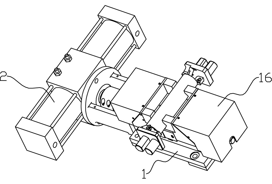
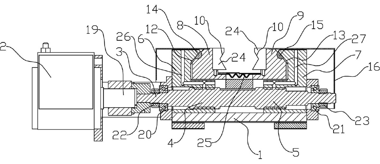
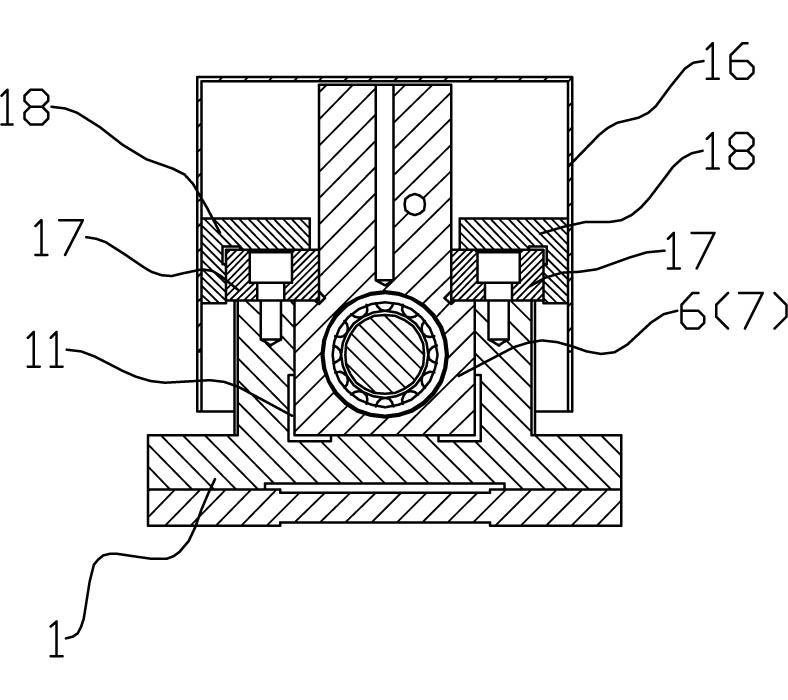
[0016] refer to Figure 1 to Figure 3 , a two-way clamping mechanism of the present invention, comprising a base 1 and a power mechanism 2, the rotating shaft 19 of the power mechanism 2 is connected with a screw 3, and the screw 3 is respectively provided with first and second threaded parts 4, 5 at intervals, The pitches of the first and second threaded parts 4 and 5 are equal and the direction of rotation is opposite. The outer parts of the first and second threaded parts 4 and 5 are fitted with first and second nuts 6 and 7. The first and second nuts 6 The first and second sliders 8 and 9 are installed on the first and second sliders 7 and 7 respectively, and the first and second sliders 8 and 9 are respectively provided with jaws 10 with opposite openings. Wherein, the power mechanism 2 is one of a rotary cylinder, an oil cylinder or a motor. Due to the adoption of the above-mentioned structure in this bidirectional clamping mechanism, the first and second nuts 6 and 7 m...


PUM


Abstract

The invention discloses a bidirectional clamping mechanism, which comprises a base and a power mechanism. A rotating shaft of the power mechanism is connected with a screw; a first threaded part and a second threaded part are arranged on the screw at intervals; and the first threaded part and the second threaded part have the same thread pitch and opposite threaded directions. A first nut and a second nut are sleeved outside the first threaded part and the second threaded part; a first slide block and a second slide block are arranged on the first nut and the second nut respectively; and opposite clamping openings are formed on the first slide block and the second slide block. Due to the adoption of the structure, the bidirectional clamping mechanism makes the first nut and the second nut move to the middle part synchronously under the driving of the screw during work, clamps columnar workpieces through the clamping openings on the first slide block and the second slide block, keeps the consistency of the center lines of the positioned and clamped workpieces with a machining tool, and improves the machining accuracy.

Description

technical field [0001] The invention relates to a fixture, in particular to a fixture for metal cutting machine tools. Background technique [0002] In the metal cutting process, it is often encountered that the shape and position accuracy of the workpiece is based on the center line of the workpiece shape, such as the boring process of the workpiece, the workpiece must be clamped and positioned by the fixture during the processing. In the prior art, this kind of fixture is double-sided clamping, one side is a fixed block, and the other side is a movable block. In use, the workpiece is placed between the fixed block and the movable block, and the fixed block is used as the positioning , so that the movable block approaches and clamps the workpiece. However, since the fixture of this structure adopts unilateral positioning, the inconsistency of the outer dimensions of the workpiece will affect the inconsistency of the centerline deviation of the workpiece positioning and cla...

Claims


Application Information

Patent Timeline
IPC IPC(8): B23Q3/06
Inventor 邝锦富
Owner 邝锦富
Why Eureka
Try Eureka