Capacitance type continuous material level sensor

A capacitive, sensor technology, applied in the direction of the liquid level indicator for the measurement of physical variables, can solve the problems such as the inability to ensure the relative fixation of the protective cover, the reduction of the service life of the sensor, and the large measurement error, and achieve stable and reliable calibration signals. Realistic, simple effects of signals and scaled signals

Inactive Publication Date: 2010-12-08
WEIHAI HAIHER TECH
View PDF5 Cites 4 Cited by
  • Summary
  • Abstract
  • Description
  • Claims
  • Application Information

AI Technical Summary

Problems solved by technology

However, first of all, the flexible metal electrode used in the main pole of this continuous capacitive sensor is a single structure, which cannot ensure that the protective sleeve and the calibration electrode on the outside of the main pole are relatively fixed to each other. When the protective sleeve and the calibration electrode rotate When the sensor is damaged, it will cause damage to the sensor; secondly, the long-term contact and collision with the material will easily cause serious wear and tear, reduce the service life of the sensor, and cannot be used in harsh environments; thirdly, this The calibration electrode of the continuous capacitive sensor is exposed outside and is in direct contact with the material, which is prone to short circuit. Moreover, because the calibration electrode is surrounded by the metal main pole, the calibration electrode will shield the corresponding section of the metal main pole. All the measurement signals of the signal, resulting in too large measurement error

Method used


Image

  • Capacitance type continuous material level sensor
  • Capacitance type continuous material level sensor
  • Capacitance type continuous material level sensor

Examples


Embodiment Construction

[0018] The present invention will be described in detail below in conjunction with the accompanying drawings and embodiments.

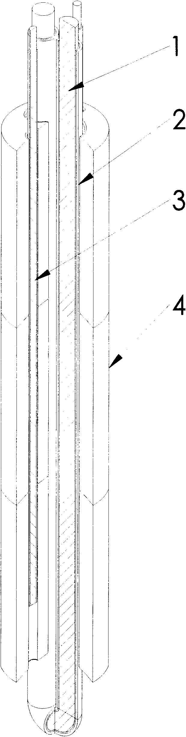
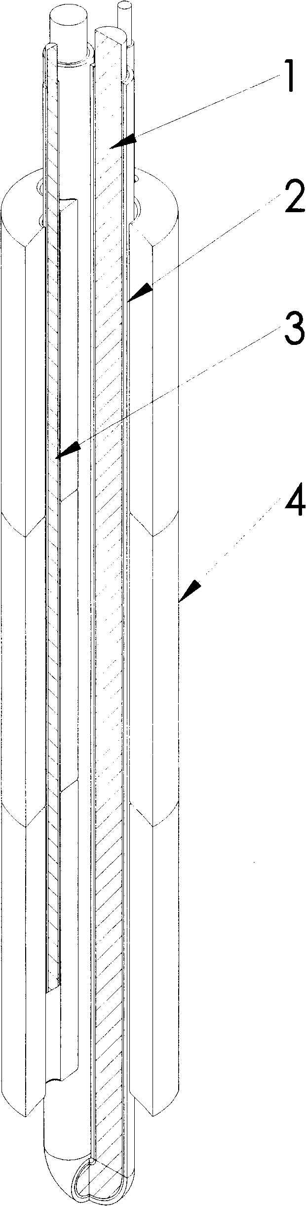
[0019] from figure 1 , figure 2 , image 3 , Figure 4 , Figure 5 It can be seen from the figure that the present invention is provided with a metal main pole 1, the upper end of the main pole 1 is provided with a fixed flange, and the upper part of the flange is provided with a capacitive transmitter 5 for processing electrical signals, and the main pole passes through an insulating pad Insulated and fixed with the flange plate and the silo, the main pole and the silo wall are respectively one pole, forming a variable medium continuous capacitor, and its upper end is electrically connected with the capacitance transmitter 5, and the metal main pole 1 is a flexible conductive steel cable A double-strand structure folded in half from the bottom, the outer side of each flexible conductive steel cable of the metal main pole 1 is covered with a flex...


PUM


Abstract

The invention relates to a capacitance type continuous material level sensor provided with a metal main pole, at least one auxiliary measuring electrode and a plurality of insulating jackets, wherein the metal main pole is in a double-strand structure formed by folding a flexible conducting steel cable from the bottom end, the outer side of the metal main pole is sleeved with a protective layer comprising a plurality of insulating jackets, and the metal main pole passes through two main pole through holes of the insulating jackets; each auxiliary measuring electrode is formed by one flexible steel cable accompanied with the main pole; and each insulating jacket is made of a cylindrical high-strength insulating material, can be in a composite type structure and is formed by combining a metal sleeve on one insulating base, a plurality of through holes are axially arranged in the insulating jackets and are respectively two main pole through holes and at least one auxiliary measuring electrode through hole. The capacitance type continuous material level sensor has the advantages of simple structure, long service life, strong shock-resisting capacity and wear-resisting capacity and true, accurate and reliable signal measurement and calibration, and can continuously and accurately measure the material levels in bins.

Description

technical field [0001] The invention relates to an improved device of a material level measuring device, in particular to a capacitive continuous material level sensor which measures the height of materials in a contact manner. Background technique [0002] In the field of instruments and meters, it is one of the more practical methods to measure the solid materials in the silo and use capacitive sensors for measurement. The applicant's patent 00215270.3 discloses a continuous capacitive sensor, which is provided with a metal flexible main pole, the upper end of the main pole is provided with a fixed flange, and the upper part of the flange is provided with a capacitance transmitter. The blue plate and the silo are insulated and fixed, and the main pole and the silo wall are respectively one pole, forming a variable medium continuous capacitor. The outer side of the main pole is wrapped with a flexible insulating layer, and the outer side of the flexible insulating layer is ...

Claims


Application Information

Patent Timeline
IPC IPC(8): G01F23/26
Inventor 王其明于浩业程国永李文琦朱更君
Owner WEIHAI HAIHER TECH
Why Eureka
Try Eureka